This thread has been locked.

If you have a related question, please click the "Ask a related question" button in the top right corner. The newly created question will be automatically linked to this question.

TMS320F28377S: EPWM IN SIMULINK

Part Number: TMS320F28377S

Hi,

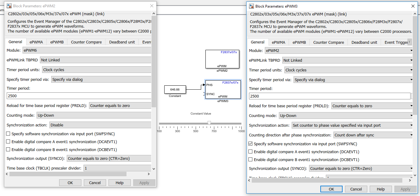
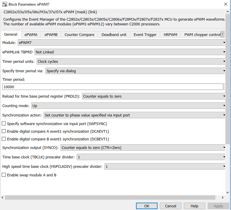
I am using to extract 4 pairs of EPWM signal, where PWM7 and PWM8 behaves as master and other 2 pairs as slave in MATLAB and Simulink.I am able to control the phase shift by activating TBPHS tab and by selecting an option to be internally written phase shift value. But providing the same phase shift through an externally connected slider, doesnot yield any phase shift. I want to change the phase shift real time and to control it, that's why i have choosen externally controlled option.

Please provide any solutuion to this.

Thanks

  • Dear D Mishra,

    We have reached out to our contact at Mathworks to help resolve this issue. Thanks for your patience as we await a response.

    Thanks,
    Krishna
  • Hi Mishra,

    Please provide details on MATLAB version you are using and if possible attach the model which you are working with.

  • Hi Venkatesh,

    I have attached a snapshot of 2 PWM pair, i am using in MATLAB2017a.I have also enabled the HRPWM option, but realtime phase control is not obtained by connecting an external slider gain for the constant input to ePWM3 (ePWM 2 ,the synchronisation action is disabled to make it as the reference PWM signal).

    Thank you

  • Hi Mishra,

    From what I see from your model the SYNC input port is not connected which happens to be the source for phase synchronization. Since the syncs source is specified as software you may want to consider adding a signal at this port. 

    Do you see the same behavior when HRPWM option is disabled? How about specifying the Phase value via dialog than input port.?

    Please let us know if any of these settings helps you see some results.

  • Hi Mishra,
    Were you able to resolve the issue after the response from Mathworks? Please let us know.
    Cheers!
    Krishna
  • Hi,

    Sorry for delayed response.

    Please understand the problem, that i am facing in simulink while using the TI28377S controller and suggest me the solution. 

    I am using two ADC channel as A3 and A4 to measure the source voltage and current, where a single phase ac is connected with a rectifier load.

    The details of ADC A3 and A4 are attached as below.

    latter from the ADC measurement,i estimate the quadrature component for each voltage and current by providing discrete sampling delay and an integrator.

    The issues, that i am facing are:

    1. If i change the integrator gain in voltage ADC, then current quadrature component also changes, though i use two isolated ADC for both of them.

    2. Suppose i change some integrator gain in current ADC, then the PLL, connected through voltage ADC gives wrong result.

    3.Is it a necessary condition to make similar ADC channel as per the ADC SOC, i.e. for SOC3---ADCA3; SOC4--ADCA4 etc. , or it can be different.

    In a brief, what i observe is, in real time mode if i change any value with the integrator, then the discrete delay that i have connected with individual ADC doesnot work properly.Is it due to the interrupt that i have not specified or due to the SOC triggering that i have given as software. Should i change the datatype from double to Uint16, as given in some Matlab example.

    Please suggest me the solution in this regard.

    Thank you

  • Hi Mishra,

    Please help understand, Is the ePWM issue reported earlier is related to the ADC issue reported now? Do let us know if you could get around the ePWM issue?

    Regarding the ADC issue as reported, I am not sure if I fully understand the plot here. But I can answer few questions you asked around ADC.

    1.Is it a necessary condition to make similar ADC channel as per the ADC SOC, i.e. for SOC3---ADCA3; SOC4--ADCA4 etc. , or it can be different.?

    Answer: No, it is not hardwired that way. You can configure any SOC for any channel in the given module. For example you can have 2 ADC blocks in simulink and configure each of them to SOC0 but different module A and B. However if you keep the module same, then the blocks cannot have same SOC. Each block represents a unique SOC for the given module. For the given ADC block you can configure any ADC channel to get sampled from given SOC. You can have multiple ADC blocks with different SOC's and same channel selected in each block.

    2. Interrupt based SOC trigger gives tighter control on enabling the ADC sampling to sample at precisely the point of interest. That are multiple hardware trigger source which can start the ADC conversion. For your application you need to figure out which one helps best. When using the software trigger the sampling is happens periodically based on the sampling rate of the model. Hence external events that can change voltage let's say Duty cycle change cannot be tangibly captured using software trigger. Hence in this case configuring an ePWM to trigger the ADC on say every PWM cycle can help.

    3. The ADC block returns raw count of the conversion which is like 0-4095 of value for a 12bit ADC. In this case uint16 will suffice. 

    Hope this helps.

  • Thank you Venkatesh for your valued response on ADC.

    Let me first tell that the PWM issue is not over yet. As my EPWM issue is concerned, i need to vary the phase shift by an external port in real time. To achieve this i have connected a slider gain as my input port. But unfortunately the input port only take constant values rather to say fixed values in the port, whereas i need to vary phase shift, which is continuously controlled by some external parameters or control action.

    Please resolve the issue.I have connected the related figure, kindly verify it. Regarding the ADC, i appreciate your response.For further discussion about ADC, please provide me a link.

    Thank you