This thread has been locked.

If you have a related question, please click the "Ask a related question" button in the top right corner. The newly created question will be automatically linked to this question.

CCS/TMS320F28377D: Converting SDFM output into mVolts

Part Number: TMS320F28377D
Other Parts Discussed in Thread: AMC1306EVM, C2000WARE, AMC1306E25, AMC1311

Tool/software: Code Composer Studio

I’m trying to configure the Delfino F2837xS CPU with AMC1306EVM Sigma-Delta module configured for Manchester encoding. I’ve successfully received the 16-bit data from the SDFM, and the data is consistent. My current problem is the values I receive.

When supplying 250 mV, I read from SDFM only about 4400, which is a lot less than expected, since it’s 16-bit signed value with values up to 32768, and since I supply values close to the maximum supported by the evaluation board, I would expect output close to available maximum as well. (Manchester encoding is not the one that causes the problem here; I've achieved the same results with Mode_0). Same happens with negative values; I supply -250 mV and receive a negative number close to -4400. The results are consistent; if I supply voltage between -250 mV and +250 mV, I receive output between -4400 and +4400, proportionally. If the input voltage is out of the [-250; +250] scope, the output grows proportionally with higher inaccurancy, until I leave the [-320; +320] mVolts range of the evaluation board.

I have forged a simple proportion and successfully interpret the value I read into mVolts, it gives readings that fall close to the actual supplied voltage. But the range [-4400; +4400] I receive from the DSP’s SDFM is too coarse for fine current measurement, and small differences in the DSP’s SDFM output result in error of ±5 mV after the interpretation. In other words, for input of 100 mV I receive values that fall between 95 and 105 mV in Gauss’ bell. This noise is not a result of the input; it happens even when the input is short-circuited and gives strict 0. The wires are short and checked for external interference. Anyway, the ±5 mV difference would be way over the noise ratio.

The formula I forged is mVolts = 320.0 * (SDFM_output - 50.0) / 5250 for positive input (for negatives it's a bit different). As I said, it works relatively well, save for the ±5 mV error.

On the other hand, when using the formulae received from TI and not the one that follows from proportion, the output in mVolts don’t even fall close to the actual input. It comes out much lower than expected. (Just like the output  from the Sigma-Delta filter is way lower than expected).

The formula I received is: Vin = 320.0 * { (2 x SDFM_output) / ((256 * 256 (for SINC1) ) - 1)}

Would you please advise on what could be done about the interpretation?

  • Alexey,

    Please provide following information

    1) What is the filter type used?

    2) What is the DOSR settings?

    3) Are you using PWM sync option to synchronize the filters?

    4) Is this a custom board (or) are you using control card + AMC EVM setup?

    Assuming you are using filter type = Sinc3 &  DOSR = 256 (based on your earlier post), digital filter output of 4400 (decimal) when applying +250mv is clearly incorrect. Did you check your hardware setup? We first need to cross this hurdle before we worry about digital filter output interpretation.

    Regards,

    Manoj

  • Manoj,

    1 and 2) The configuration is as follows:

    Sdfm_configureInputCtrl(gPeripheralNumber, FILTER1, MODE_2);

    HLT = 0x7FFF; //Over value threshold settings
    LLT = 0x0000; //Under value threshold settings

    Sdfm_configureComparator(gPeripheralNumber, FILTER1, SINC3, OSR_32, HLT, LLT);

    Sdfm_configureData_filter(gPeripheralNumber, FILTER1, FILTER_ENABLE, SINC3, OSR_256, DATA_16_BIT, SHIFT_9_BITS);

    3) PWM11 CMPC is used to synchronize the filter. Synchronization works, I checked it.

    4) We are using control card and AMC. I'll update the thread with schematics and a picture later.

    Thanks,

    Alexey.

  • Alexey,

    Thanks for sending the configuration.

    With filter settings of Sinc3, DOSR = 256, (16 bit mode) and with

    SD-modulator differential input = +250mv, you can expect digital filter output value around 0x63FF

    Whenever PWM11.CMPC event resets the FILTER module, you are expected to get 2 incorrect samples (for sinc3) before you correct filter output. I'm wondering whether you're waiting long enough to read the correct filter result output. After you receive PWM11.CMPC event, you need to wait for Latency of Sinc3 filter + 5 SDCLK cycles before you read the filter results.

    As you are working on control card + EVM setup, I would advice you to run the below example which doesn't use PWM sync option. If you get incorrect results even in this example, then it should most likely be hardware setup issue. If so, then it should be timing related issue which can be easily corrected from software side.

    <C2000Ware>\device_support\f2837xd\examples\cpu1\sdfm_filters_sync_cpu\cpu01

    Regards,
    Manoj
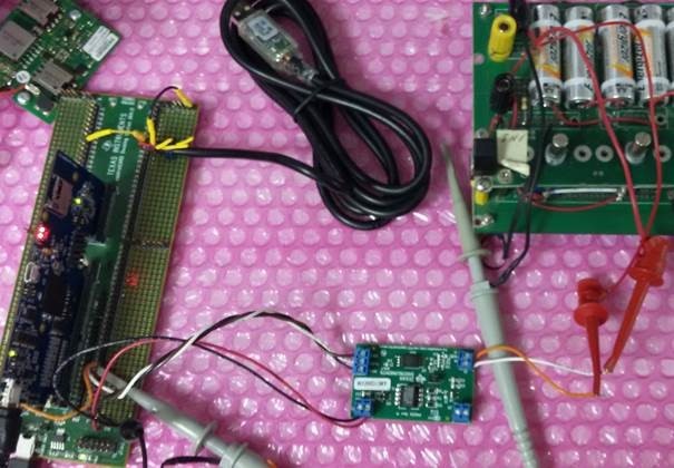
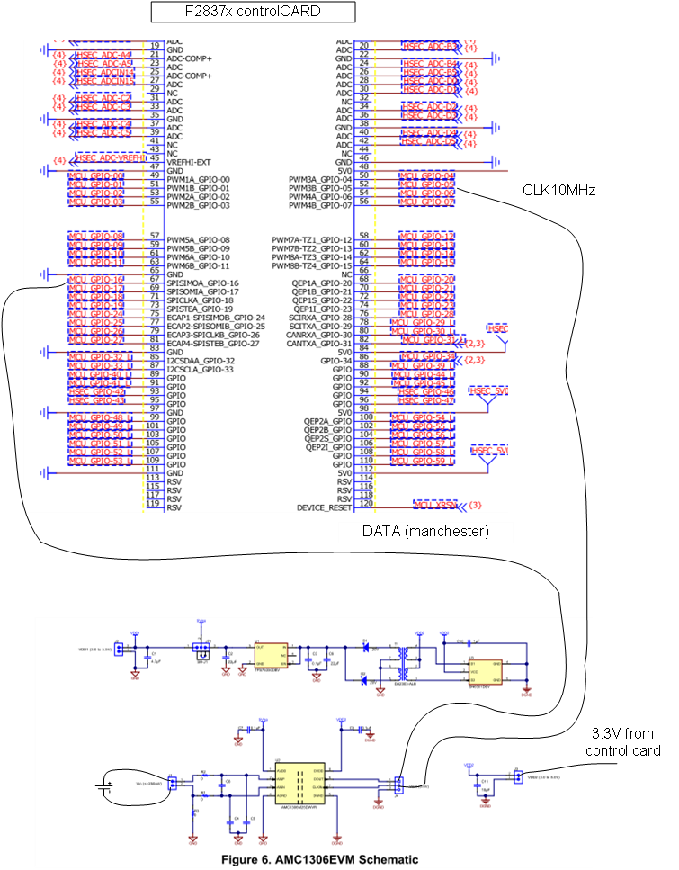
  • Pictures and schematics:


  • Alexey,

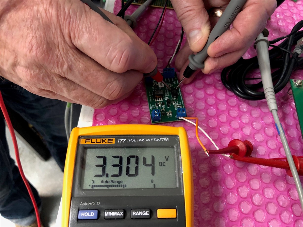
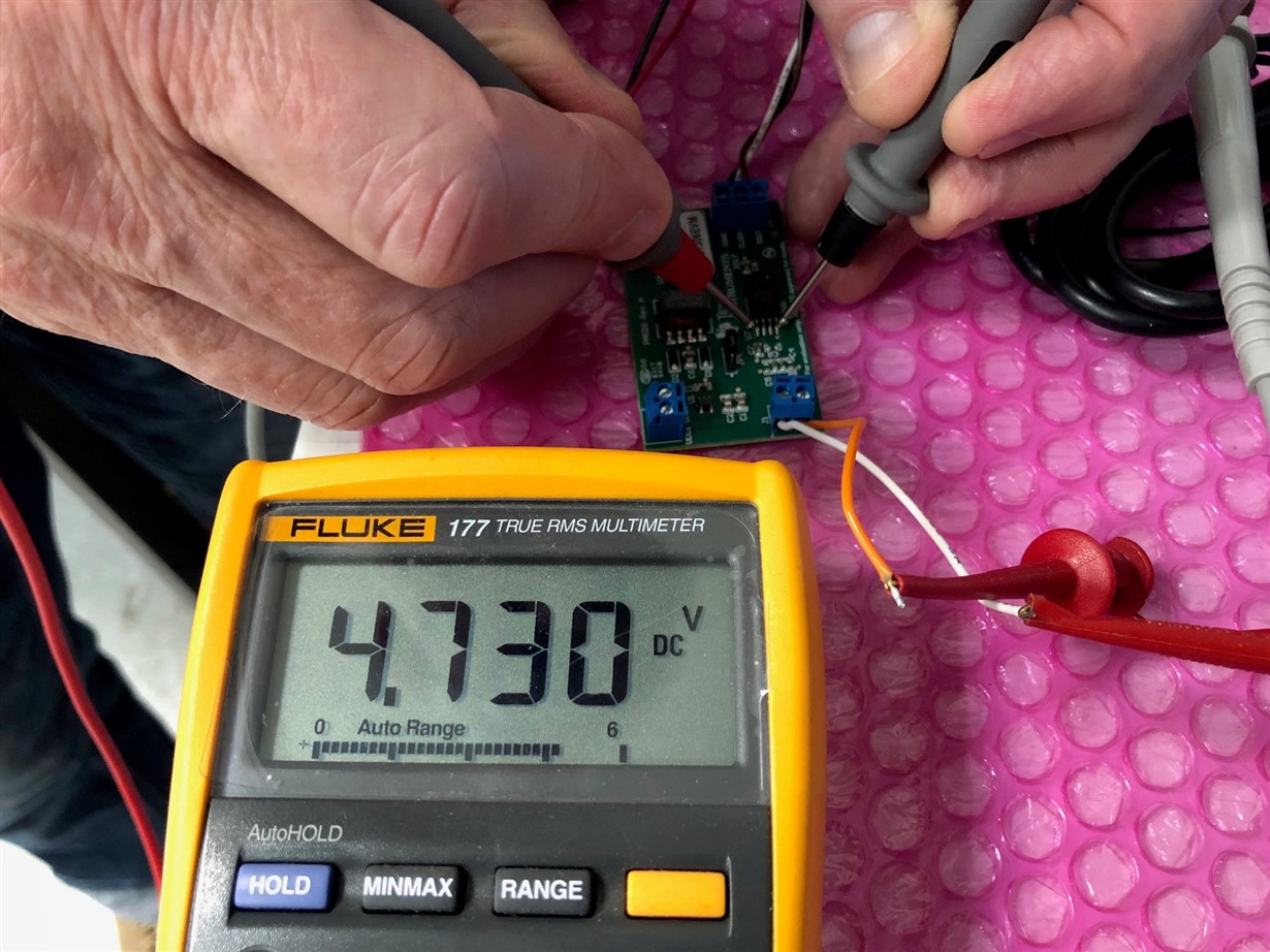
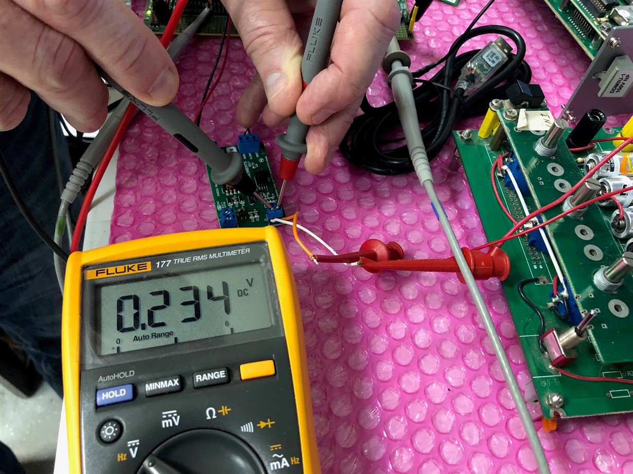
    How are you ensuring that voltage difference between terminals of J1 of AMC1306EVM = +250mv? Did you confirm by probing J1 using multimeter?

    Regards,
    Manoj
  • Alexey,

    Another thing to check is to make sure whether you are powering up the AMC1306 EVM correctly?

    Regards,
    Manoj
  • Hi Alexey,

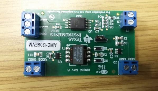
    Can you also please verify the AMC1306 part number of the EVM, we have not released the Manchester version of the evaluation module. If it's a stock EVM, you have the CMOS output version on the board.
  • Alexey,

    One more checkpoint would be to make sure SD-Cx and AMC1306 CLKIN are working at the same frequency. If both are not in the same frequency, you might miss samples which can result in wrong digital filter output. I believe PWM output is clocking both SD-Cx and AMC1306 CLKIN. But, you pictorial representation doesn't show that.

    Regards,
    Manoj

  • Manoj,

    1) You are right, we have replaced the Sigma-Delta modulator on the evaluation board with a component _with_ Manchester encoding.

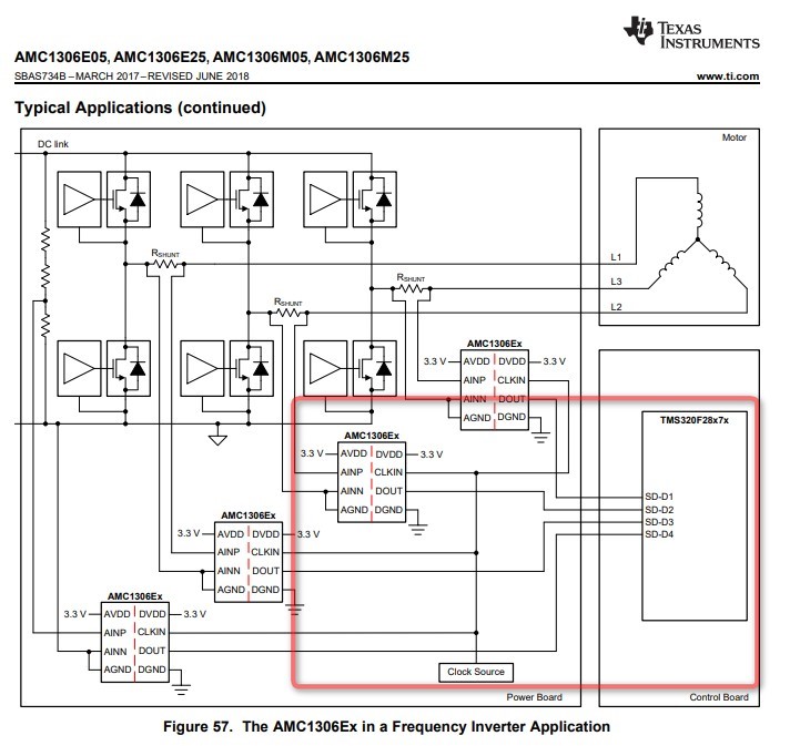
    This is the picture of the datasheet of the Sigma-Delta modulator that we are using (AMC1306E25). The letter "E" defines it as capable of Manchester encoding:

    The clock source (10 MHz) is ECAP without connection to SD-C.

    We have replaced the Sigma-Delta modulator from the stock version of Evaluation Board with this component. However, the very same problem existed with the stock version of the component, which was used with MODE_0. (Actually, replace of the component with change from MODE_0 to MODE_2 produces exactly same results). When we worked with the stock component, we have provided the clock to SD-C input with physical connection (from GPIO05 configured as ECAP output to GPIO17 configured as SD-Clock input).

    It is possible to revert back to stock version of the modulator, the SD output will still be in range of about 4500; this is from where we turned to Manchester.

    2) We are powering the evaluation board with 3.3V from the control board. I did not show the power lines in the schematics above, it's my fault.

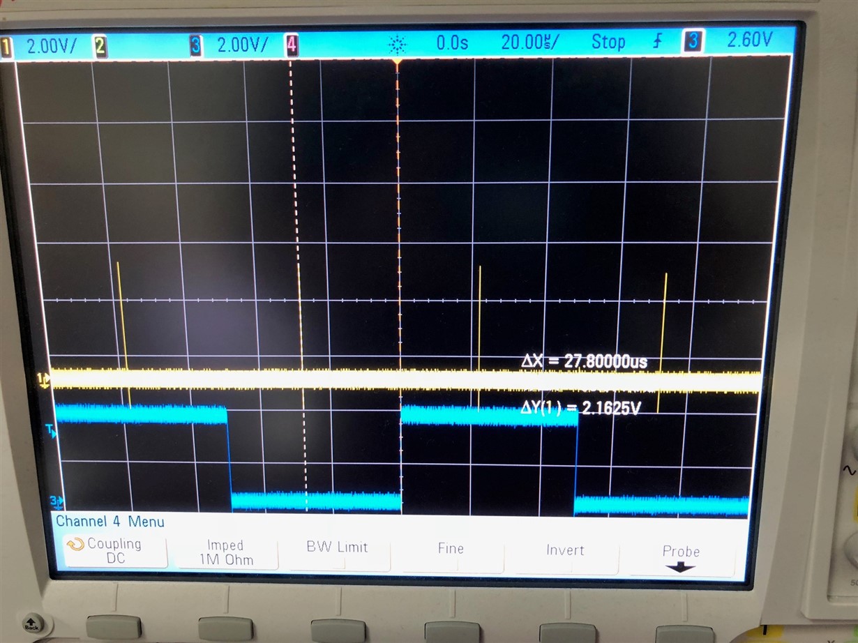
    3) We are waiting 27.8 usecs between the SDFM reset and the reading, which is performed according to the "data ready" interrupt.

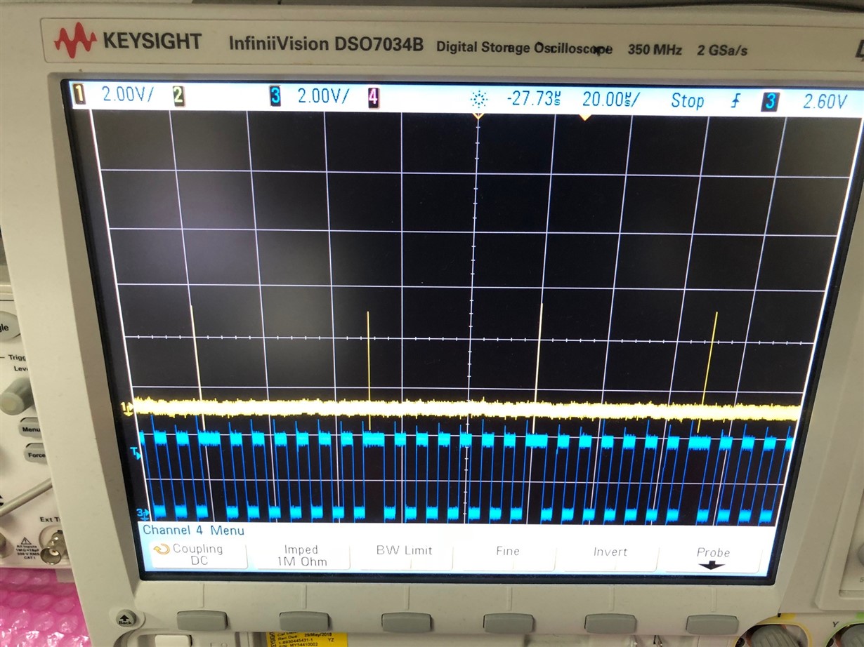
    The yellow channel is configured to represent the SDFM reset.

    PWM11 is configured as up-down PWM with EPWM_TIMER_TBPRD = 2500. Yellow probe is PWM11 channel A, configured to (*EPWM[gPWM_number]).CMPA.bit.CMPA = EPWM_TIMER_TBPRD - 1 (the -1 is to make the signal bolder on the scope). The CMPC used to reset the SDFM is configured as (*EPWM[gPWM_number]).CMPC = EPWM_TIMER_TBPRD; - therefore, since they use the same counter, "SDFM Reset" event occurs exactly in the middle of the tiny yellow peak.

    The blue channel is a GPIO toggled at Sigma-Delta reading function, which is called from a "data ready" interrupt:

    __interrupt void Sdfm1_ISR(void)
    {
    uint32_t sdfmReadFlagRegister = 0;

    sigma_delta_read();

    .....}

    void sigma_delta_read(void) {

    static unsigned int loopCounter1 = 0;
    int32_t read_data;

    GpioDataRegs.GPFTOGGLE.bit.GPIO161 = 1;          <=== This is the toggle of the blue channel.

    The difference between them is 27.8 usecs, which should be enough.

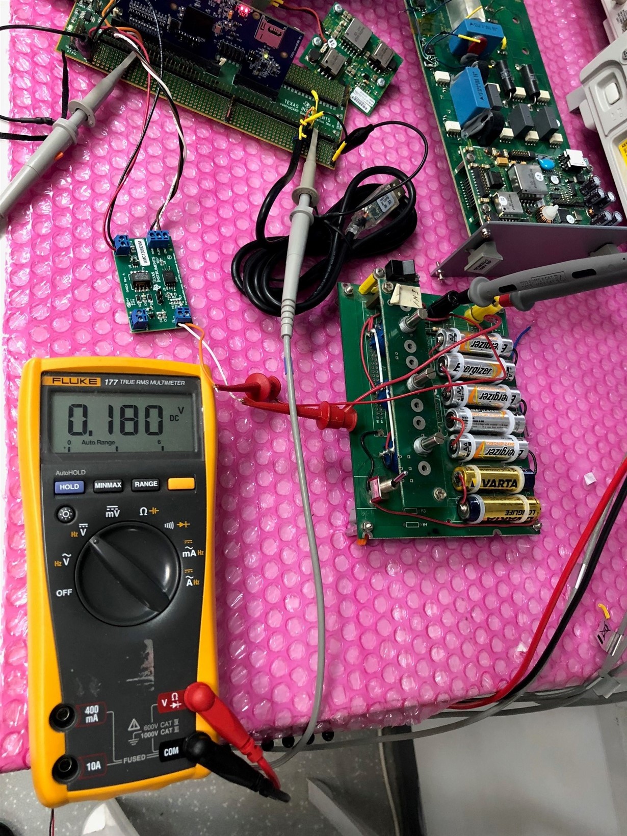
    4) The hardware power is as follows:

    This is the digital part powered from the DSP evaluation board.

    This is analog part powered from internal EVB power supply.

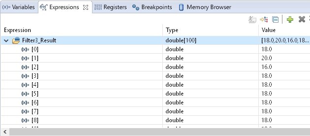
    This is an analog input example taken from an external DC power source (batteries pack) for example. The corresponding raw data read from the SDFM is:

    obtained with

    void sigma_delta_read(void) {
    
    	static unsigned int loopCounter1 = 0;
    	int32_t read_data;
    
    
    	GpioDataRegs.GPFTOGGLE.bit.GPIO161 = 1;
    	read_data = SDFM1_READ_FILTER1_DATA_16BIT;
    
    	Filter3_Result[loopCounter1] = read_data;

    5) I think it would be convenient if you reproduce our setup (with the stock version of the EVM - including SD-C clock) and use the same software in order to check the correlation of the results.

    Thanks,

    Alexey.

  • Manoj,

    Just for reference, with SDFM filter configured as 32 bits —

    Sdfm_configureData_filter(gPeripheralNumber, FILTER1, FILTER_ENABLE, SINC3,
                                  OSR_256, DATA_32_BIT, SHIFT_0_BITS);
    
    void sigma_delta_read(void) {
    
    	static unsigned int loopCounter1 = 0;
    	int32_t read_data;
    
    	GpioDataRegs.GPFTOGGLE.bit.GPIO161 = 1;
    	read_data = SDFM1_READ_FILTER1_DATA_32BIT;
    	Filter3_Result[loopCounter1] = read_data;
    

    — And input of 180 mV (verified with a multimeter as shown on one of the photos above) I receive the following data in the Filter3_Result[]:

    Thanks,

    Alexey.

  • Alexey,

    You aren't waiting long enough to get correct filter result. Please check the explanation below.

    After PWM reset to SDFM, you have to wait for atleast (Latency of SincFilter + 5 SD-Cx period) = 77.3us to read correct filter result for filter type, OSR and SD-Cx frequency you have chosen. Calculations are shown below:-

    Filter Type = Sinc3
    DOSR = 256
    SD-Cx = 10 MHz

    Latency of Sinc filter = Order of Sinc filter * (DOSR / SD-Cx)
    = 3 * (256 / 10 MHz)
    = 76.8us

    5 SD-Cx period = (5 / 10 MHz)
    = 500ns

    Wait time to read correct filter result after PWM reset = 76.8 us + 500 ns = 77.3 us

    Regards,
    Manoj
  • Manoj,

    Ok, I moved to SINC1 and reduced the OSR to 32.

    Sdfm_configureData_filter(gPeripheralNumber, FILTER1, FILTER_ENABLE, SINC1,
                                  OSR_32, DATA_16_BIT, SHIFT_0_BITS);

    I should not receive any incorrect samples. However, I manually skip 3 first samples after reset, by introducing a global variable which is set to value 3 at the PWM interrupt (SDFM reset) and either reducing its value in SDFM interrupt handler or calling sigma_delta_read()

    int skip_samples = 3;
    
    __interrupt void Sdfm1_ISR(void)
    {
        uint32_t sdfmReadFlagRegister = 0;
    
        if (skip_samples == 0)
        {
        	sigma_delta_read();
        }
        else
        {
        	skip_samples--;
        }
    . . . .
    }
    
    __interrupt void PWM11_Comparator_C_UP_DOWN_ISR (void)
    {
        skip_samples = 3;
    . . . .
    }

    This is how the scope looks like now:

    The input value is 180 mV:

    However, the readings I get from the SDFM are very low and noisy (note values from 16.0 to 20.0):

    Would you please advise on the next step in debugging?

    Thanks,

    Alexey.

  • Alexey,

    I'm not sure why you ignored my suggestion in earlier post. For Sinc3 OSR = 256 and SD-Cx freq = 10 MHz, if you wait for 77.3us after PWM reset your problem will be resolved. You need to change PWM configuration to do that.

    For your question on Sinc1 filter, OSR = 32, I want to tell you that filter resolution of Sinc3 filter is much superior that Sinc1. Please check Pg:26 Figure 55 www.ti.com/.../amc1306e05.pdf. Since the filter resolution is so low, it is expected to be noisy like you observed.

    Regards,
    Manoj
  • Manoj,

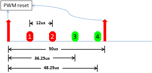
    We can't afford delay of 77 usecs. We have strict requirement of 50 usecs of time overall, including at least 2 measurements of voltage. After 50 us, the voltage is changed, and we have to reset the SD filter in order to discard old data read in the previous cycle. Therefore, we can only operate in range of up to 50 us. And in this period of time we have to measure voltage twice, which leaves even less time for the SD to settle. We were even considering the option of reducing the work cycle from 50 us to 25 us or less, — in this case, as I see it, Sigma-Delta will not be the ideal voltage measurement solution.

    I understand that Sinc1 is noisy, but aren't the values I read too low even for noisy environment? Input of 180 mV, output of 16-20 with median at 18, — isn't the output too low for this input?

    Thanks,

    Alexey.

  • Alexey,

    I understand that your system requirements are different. But, to resolve your first question in this forum post, can you try waiting for 77.3us before you read SDFM digital filter output? When you apply +250mv, SDFM filter output should be around 25600 (for 16 bit configuration) and -25600 for -250mv. This will confirm that both your hardware and software setup is good.

    For sinc1, OSR = 32, differential input = 180mv, theoretical expected data is 17.7 (18 approx). So, the value you read is not too low.

    Regards,
    Manoj
  • Hi Alexey,

    Maybe I missed this in an earlier thread but what is the nature of the voltage you are trying to measure? Can you increase your AMC1306 clock rate to 20MHz? With the original 256 OSR and SYNC3 filter, you should get valid data at ~78kSPS or new data every 12.8uS. I'd like to try and understand why it's necessary to continuously reset the SD Filter to 'discard old data'. Would you be better off using an isolated amplifier like the AMC1311 and then feed the analog output voltage into the SAR ADC of the C2000 controller?
  • Manoj,

    You are right, waiting for 81.6 usecs between the reset and the reading with input of +250 mV gave output of 25577-25581 from the SD filter.

    Thanks,

    Alexey.

  • Alexey,

    Great to know that. This confirms that your hardware set up is correct and the digital filter output observed correlates well with theoretical expected output.

    Now, coming to your application requirement, as Tom suggested you need to increase the SD-Cx frequency to 20MHz, this does two things: 1) It provides better ENOB performance for the same filter type / OSR setting when compared with 10MHz. 2) Reduces the data rate and latency of Sinc filter.

    If you are planning to use PWM sync feature to reset SDFM filter channels every 50us and you want to read correct 2 filter data when using Sinc3 filter and OSR = 240

    SDCLK = 20 MHz

    OSR      = 240

    Data rate of Sinc1 / Sinc2/ SincFast / Sinc3 filter = (240 / 20 MHz) = 12.0 us

    Latency of Sinc1 filter =     (240 / 20 MHz) = 12.0 us

    Latency of Sinc2 filter = 2*(240 / 20 MHz) = 24.0 us, where 2 is order of Sinc filter

    Latency of Sinc3 filter = 3*(240 / 20 MHz) = 36.0 us, where 3 is order of Sinc filter

    Latency of SincFast filter = 3*(240 / 20 MHz) = 36.0 us, where 3 is order of Sinc filter

    Within 50us window, you should be able to read 2 correct filter data when using Sinc3 and OSR = 240. I added 250ns to account for 5 SD-Cx period.

    Regards,

    Manoj

  • Manoj,

    We managed to increase the SD clock to ~18 MHz, that reduced times of waiting even more. Unfortunately, we can't increase the SD clock to 20 MHz in current setup, since we're using eCAP in PWM mode for the clock generation, and the next value it can generate after 18 MHz is about 22 MHz, which is out of limits supported by the hardware. We are considering using an external oscillator for that purpose, though.

    Thank you for your support!

    Alexey.

  • Alexey,

    Glad to know you issue is resolved.

    I'm closing this thread. If you have new questions open a new thread.

    Regards,

    Manoj