


Part Number: TMS320F28335
Setup:
TI F28335 communicates via parallel bus (XINTF) with the following nodes:
- TI C6747
- XINTF zone 7
- over HPI
- address + data multiplexed
- EtherCAT module
- XINTF zone 6
- separate address and data lines
- external ADC
- XINTF zone 0
Problems:
1. First High-Word read = 0x0000
The first High-Word is read out with 0x0000 each time a new address is set.
This happens:
- in auto-increment-mode:
- the first read access after setting a new start address
- in NON-auto-increment-mode (i.e. when reading a single value):
- every time
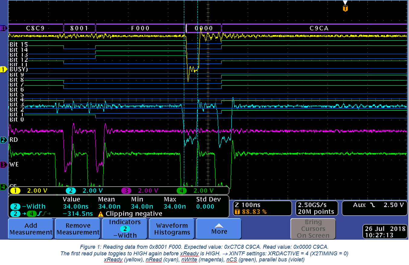
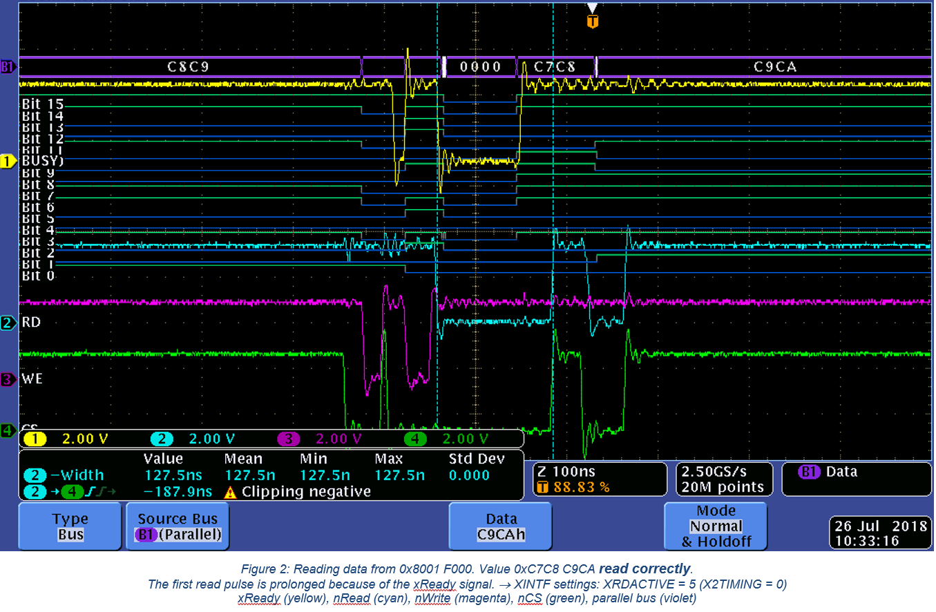
→ Reason for this behavior is probably a wrong reaction/function of the xReady signal. The F28335 finishes its read request although it receives a BUSY signal from the C6747.
This behavior can be influenced by changing the XRDACTIVE setting.
a) With setting XRDACTIVE = 4, the xReady signal is ignored. (see Figure 1)
b) With setting XRDACTIVE = 5, the F28335 reacts correctly on the xReady signal. (see Figure 2)
|
Question 1 |
Why does the slight change of XRDACTIVE from “4” to “5” ticks change the reaction on the xReady signal?
|
|
|
|
|
Question 2 |
So far, we always use asynchronous mode for this XINTF (READYMODE = 1). |
2. Timing restrictions for XINTF
Before getting to the results above, the following settings for the XINTF (Zone 7) have been used:
|
Parameter |
Description |
Value |
|
XWRLEAD |
Write LeadTicks |
1 |
|
XWRACTIVE |
Write ActiveTicks |
2 |
|
XWRTRAIL |
Write TrailTicks |
2 |
|
XRDLEAD |
Read LeadTicks |
3 |
|
XRDACTIVE |
Read ActiveTicks |
4 |
|
XRDTRAIL |
Read TrailTicks |
3 |
|
USEREADY |
Use XREADY Pin |
1 |
|
READYMODE |
Enable the XREADY sampling |
1 |
|
X2TIMING |
Double the TimingSettings |
0 |
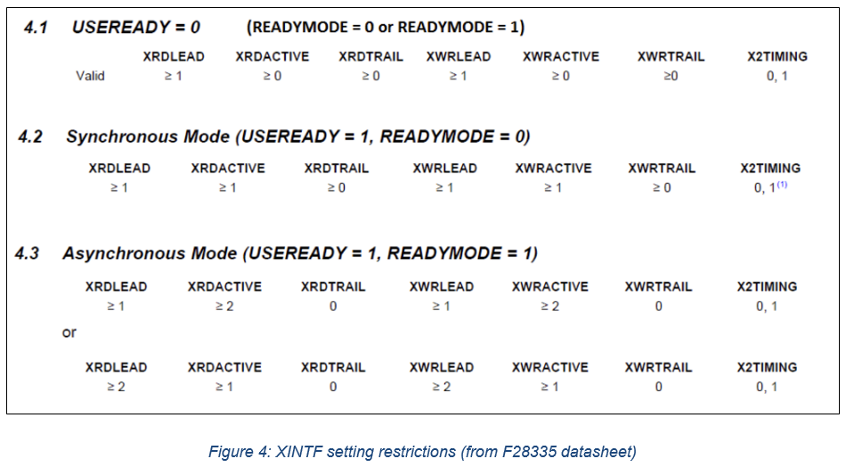
After checking in the datasheet, it seems this is an invalid configuration (see Figure 3).

Although the criteria XRDTRAIL == 0 AND XWDTRAIL == 0 was not met, the communication behavior stayed the same.
i.e. HIGH-word errors when XRDACTIVE = 4 and no HIGH-word errors with XRDACTIVE = 5.
|
Question 3 |
Can you explain how this wrong setting influences the communication? The reason I ask this is, that for another XINTF zone we must violate the above rules to get a working communication. |
The XINTF settings for communication with the attached EtherCAT Board (Zone 6) are as follows:
|
Parameter |
Description |
Value |
|
XWRLEAD |
Write LeadTicks |
3 |
|
XWRACTIVE |
Write ActiveTicks |
7 |
|
XWRTRAIL |
Write TrailTicks |
3 |
|
XRDLEAD |
Read LeadTicks |
2 |
|
XRDACTIVE |
Read ActiveTicks |
7 |
|
XRDTRAIL |
Read TrailTicks |
2 |
|
USEREADY |
Use XREADY Pin |
1 |
|
READYMODE |
Enable the XREADY sampling |
1 |
|
X2TIMING |
Double the TimingSettings |
0 |
When changing XWRTRAIL to “0” as implicated, the communication does not work anymore. Data is then written incorrectly to the EtherCAT module.
|
Question 4 |
Can you please explain in more detail the timing requirements for XINTF of C2000 (trail, active, lead ticks, …)? |
3. Read request from wrong address
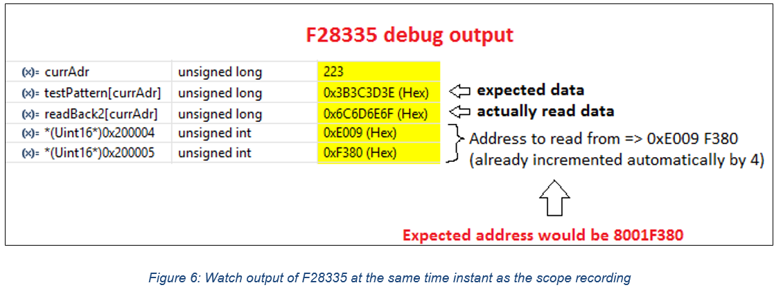
Another issue we came across is that the address where the data is read from the C6747 is corrupted because of wrong XINTF settings. We cannot see the issue on the scope, but when checking the F28335 registers, it is clear, that the wrong address is set.
Error example:
On C6747 @address 0x8001 F37C the value 0x3B3C 3D3E is stored. When reading from this address, the data 0x6C6D 6E6F is read instead (incorrectly).

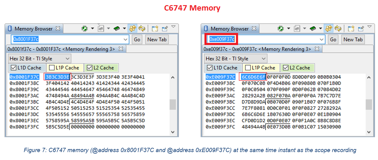
The described problem could be solved by increasing the XWRLEAD from “1” to “3”. On the scope, however, the timing when the address bits toggle does not really change in relation to the write pulse start. But in the test firmware no communication errors occur. The increased time between CS start (green) and Write start (magenta) can be seen in Figure 8.

|
Question 5 |
Can you explain, why the change of XWRLEAD solves the issue, although timing of data/address lines seems to be unchanged in relation to Write pulse. |
For better readability the description can also be found here:


