This thread has been locked.

If you have a related question, please click the "Ask a related question" button in the top right corner. The newly created question will be automatically linked to this question.

TMDSCNCD28379D: Is a 100mΩ (0.1Ω)resistor or 100MΩ(100X10^6) connected TMS320F28379DZWT Reference pin to 22uF capacitance ?

Part Number: TMDSCNCD28379D
Other Parts Discussed in Thread: LMV344

HI everybody

I asked this question before(e2e.ti.com/.../634067).

In controlcard demo (TMDSCNCD28379D),as shown in the diagram below, we can see that the reference  pin(VREFHIA VREFHIB VREFHIC VREFHID)  is connected to the filter capacitor through 100m ohm.I thought it was a 100mΩ (0.1Ω)  connected TMDSCNCD28377D voltage reference  pin and a filter capacitor (22uF).Devin Cottier,a TI engineer, explained the reason that is "22uF is a huge load for an op-amp to drive, even one that is good at driving capacitive loads like OPA350.  The 100m ohm resistor is to ensure op-amp stability. " 

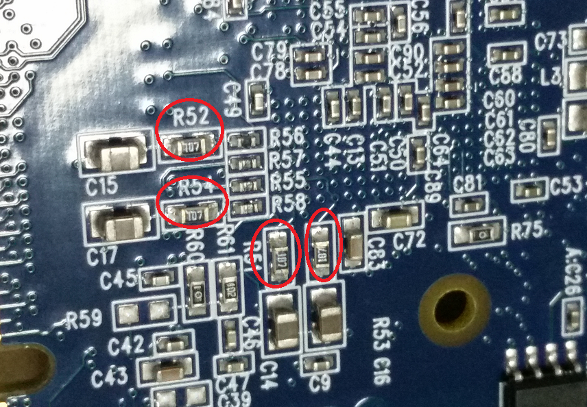
But when we bought controlCAR, we found that  The R51~R54 value is 100MΩ(100X10^6) resistors.My questions are as follows. I look forward to your help.

1, is R51~R54 100mΩ (0.1Ω)resistor or 100MΩ(100X10^6) ?Help explain why this resistance Value is used Again.

2、Why use such a large capacitance of 22uF to use a smaller capacitance, such as 1uF?

3、Which parameter of the operational amplifier determines how much capacitance it can drive?

Every question is important to me. We look forward to your reply!


  • 5.What are the requirements for the reference voltage source input of DSP to the bandwidth of the operational amplifier and the bandwidth of RC in parallel?
  • 1, it should be 100mΩ (0.1Ω). On certain revisions of ControlCard wrong value was placed. You should be able to find the topic on this on this forum. The resistance is used in order to prevent th opamp driving it to oscillate.

    2. You should be able to use smaller value if you intend to use 12 bit mode only. Otherwise large value is needed to keep the reference voltage stable during conversion process, where ADC is drawing a lot of current. There was already discussion on this forum, but I am not searching it for you as the search capabilities here are PITA.

    3. Op amps are not really qualified with the rating that would be best (transient response to step load change), so the slew rate is the best approximation of a good parameter. This was also already covered on this forum. You might want to search for posts from Chris Clearman as if I remember correctly he was involved in the debate.

  • Thank you for your reply. In my own schematic, the operational amplifier I use is lmv344.How do I calculate how much R51 resistance value ? Is this resistance larger than 0.1 or smaller?
  • Sorry for the late response, anyhow I am not an analog designer, so my knowledge on this topic is very limited. Thus we only copy-pasted TI design, as most of our projects are prototypes and are not price sensitive.

    As for the resistance value it depends on opamp stability when driving capacitive loads. If the opamp is not stable enough, the resistance will be larger. But then the Vref voltage will not be as stable as it should be which will infulence the ADC results.