This thread has been locked.

If you have a related question, please click the "Ask a related question" button in the top right corner. The newly created question will be automatically linked to this question.

TMS320F28375D: above-the-rail ADC input levels and power down sequence

Part Number: TMS320F28375D


My question is related to this forum post:

https://e2e.ti.com/support/microcontrollers/f/171/t/728229 

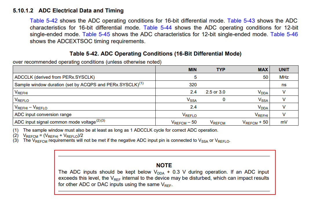
I would like to know whether the addition of a large resistance in series to the ADC input would allow the voltage on the pin to exceed VDDA  without interfering with the other ADC inputs. This is a typical case in which someone inadvertently connects the wrong signal to a board. Can we protect the circuit by limiting the current in the ADC input? I would like to ignore for now the implications related to the settling time and the performance of switching between channels.

In the same situation, what happens when the system power downs and Vdd and Vdda ramp down at different rates? Will the conversions still be valid during that period until the micro resets? Any best practices to deal with the situation?

Thank you!

  • Hi Lenio,

    Consider that the ADCIN-->VDDA diode is an ideal diode switch which conducts no current at 0.3V and infinite current at 0.30001V.

    If you add a series resistor to the ADC input, R, of any value and apply VDDA + 0.3V to the input, the ADC input pin will see the full VDDA + 0.3V and no current will flow (since no current is flowing, there is no IR drop across the R and the ADC pin sees the same voltage as the input).

    If you now increase the voltage to VDDA + 0.4V current starts flowing. Since the V drop of the diode is always 0.3V regardless of the amount of current flowing the IR drop across R is 0.1V and the current through both the diode and R is 0.1V/R.

    Based on the above, you can see that adding the series R does not affect the voltage where clamping current begins to flow (because for the R to have any effect, the diode has to be conducting already) but it can definitely limit the total current that is flowing.

    You can find the clamping current limits for the device in the datasheet in the "Absolute Maximum Ratings" table. Basically you need to limit all clamping current to < 20mA to avoid damaging the device. This could be 1 ADC input taking 20mA of clamping current or 10 ADC input and 10 GPIOs each taking 1mA.

    The same line of reasoning also applies to voltages more than 0.3V below VSSA.

    If the series R is too large to allow a practical settling time, you can also add an external set of clamping diodes. In this case you'd have Input --> R1 --> External clamping diodes --> R2 --> ADC input pin --> Internal clamping diodes. Assuming the external diodes can sink significant current, you can make R1 reasonably small. Since the V drop of the external diode = V drop of internal diode + IR drop of R2, most of the current will be steered towards the external diode even for modest values of R2.

    I'm pretty sure external diodes with large parasitic capacitance will cause some input distortion since the diode capacitance is inherently non-linear with applied voltage.

    ----

    As far as to what happens when the device is powering down, you'd ideally need an external supervisor to exert XRSn before the supplies get outside of the their operating ranges. Practically, the analog is not the limiting factor for the minimum rating on the 3.3V rails of the device. Still, we can't say for sure that the internally generated reset will assert before the voltage gets too low for the analog.
  • Devin,

    thanks for the detailed explanation - very helpful. Here is an additional aspect of my question that I wanted to cover:
    Assume an application use two ADC channels, 0 and 1. If channel 0 is subject to a voltage that is greater than Vdda, can the micro still read reliable results from channel 1?

    Thank you!
  • Hi Lenio,

    See the following note in the device datasheet:

    To be a little more specific, the disturbance occurs when the ADC samples the overvoltage signal.  When this occurs, the overvoltage feeds back into the VREF, disturbing it.  Subsequent ADC conversions on the same ADC, a DAC that shares the same VREF, or a different ADC that has its reference ganged with the ADC that sampled the overvoltage could be briefly disturbed.  

    A static overvoltage resulting in tolerable clamping current, but that isn't sampled, should not affect other channels on the same or other ADCs.