Part Number: TMS320F28377D
Other Parts Discussed in Thread: CONTROLSUITE
Dear team,
One of my customers is developing USB Bootloader program. By far they are testing the example code in Control Suite locates in "C:\ti\controlSUITE\device_support\~Utilities\usb_flash_programmer".
According to the “f28027Xd_fw_upgrade_example.txt” we have:
1) Boot the F2837xD in USB Boot Mode (see contents.txt, "Starting the MCU")
2) Connect USB from Host PC to F2837xD.
3) From the Host command line:
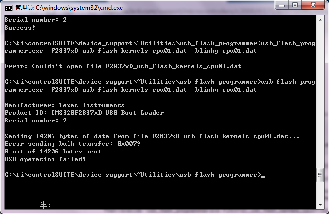
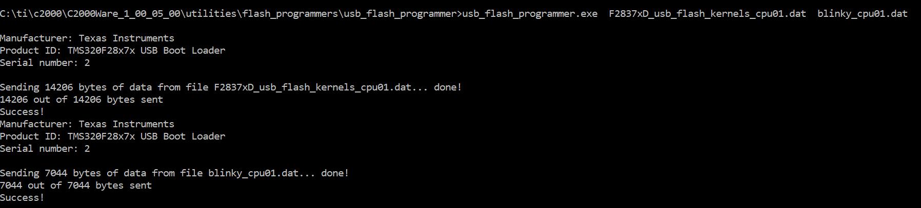
usb_flash_programmer.exe F2837xD_usb_flash_kernels_cpu01.dat blinky_cpu01.dat
Referring “Context.txt” we have:
Starting the MCU:
Reset the MCU, then write 0x0C5A to the boot mode select address (0xD00) with the debugger.
Run from the reset vector to start the USB boot loader. Connect the MCU to the PC.
So, they connected the MCU, loaded "F2837xD_usb_flash_kernels_cpu01"and wite 0x05CA to 0XD00. Then CPU Rest->Restart->Run.
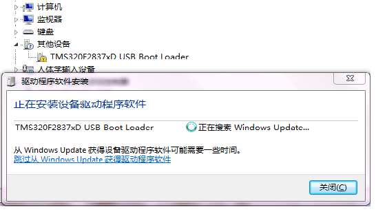
Next, connect the MCU to PC with USB, an unknown device can be found:

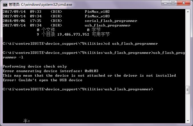
Try to run "usb_flash_programmer.exe -l", an error occurs:
Questions:
1)Did they follow the correct procedure to perform the example code? How to correctly "Run from the reset vector to start the USB boot loader" ?
2)Is the same to write 0XD00 via Memory Browser and operate Emukey and EmuBMode? I believe it should be same.
3)Is it possible to load the USB driver on PC without plug in or out the USB cable?