This thread has been locked.

If you have a related question, please click the "Ask a related question" button in the top right corner. The newly created question will be automatically linked to this question.

TMS320F280049: questions for usage of Fast Serial Interface (FSI)

Part Number: TMS320F280049
Other Parts Discussed in Thread: C2000WARE

My customers show great interest in Fast Serial Interface (FSI) in F28004x, and I have some questions about FSI as below.

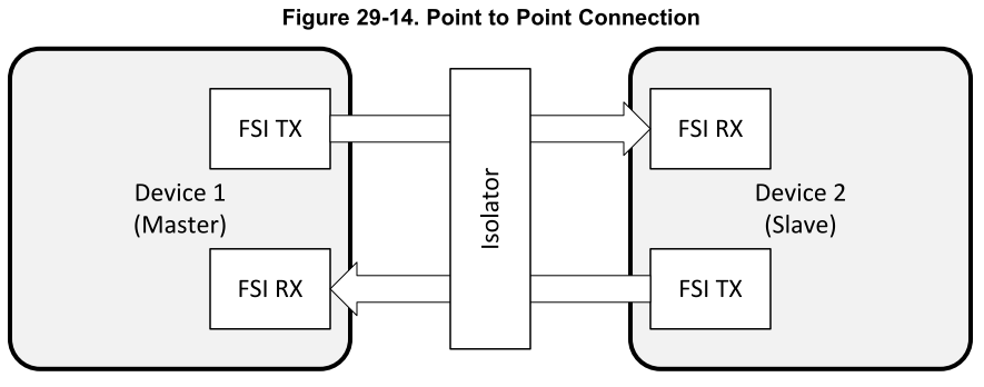
  1. FSI can achieve high speed communication across isolation, how to implement this with the delay line control? As said in the TRM, delay line elements will introduce delays on the respective lines, so I am wondering why it can be used to compensate the delay caused by isolators or signal buffers. Is there any further explanation or example project to show the usage?

        2. How to use FSI for communication of multiple devices(N)? I am evaluating two kinds of connection method:

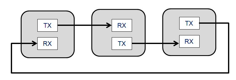
        (1) star connection(like a single-master/many-slave);        (2) daisy-chain-like connection.

         Since handshake mechanism for synchronization must take place before actual data transmission, so here comes my concern:

 1)  Is it possible to use FSI with star connection?  How can the master detect the right information sent from N-1 slaves during handshake?  Can it be done one by one?

 2) For daisy-chain-like connection, how to do the handshake?

Here is my assumption: the device 1 send a specific PING to device 2, then device 2 send another PING to device3, …., device N send a PING to device 1, so device 1 can determine whether the communication is successful by detecting whether the PING from device N is a pre-defined one.  Is this can be an effective handshake process?

 3) How to achieve the fastest communication for multiple devices with FSI?  I’d like to try DMA function, is there any other suggestion?

 4)  Do you have example project for multiple devices communication with FSI?

Looking forward for your comment, thank you!

请使用手机"扫一扫"x

  • Aki, I am putting together the answer for you. I will post it today!

  • 1. The delay line elements are on the FSIRX module. For FSI to receive the data correctly, it requires certain timing between FSIRXD1 FSIRXD2 and FSIRXCLK. When going through isolations, these signals may be delayed differently based on the nature of the isolation, and other things such as PCB layout. Enabling different amounts of these delay line elements on each of the Data or CLK lines will allow you to meet the timing requirement for correct data reception.

    We do not currently have a project in C2000ware. There is an on going project which showcases how to setup the RX delay line elements to make sure two F280049 devices can communicate at the maximum 50MHz clock rate with non-ideal delays due to different factors. It will most likely be completed in 2019.


    2. Technically speaking for F280049, only daisy chain connection + software can create a 2-way communication between multiple devices. For star connection, only one way communication can be implemented between master and N devices. Since you will only have one FSIRX module on the master, without external hardware, only one slave device will be able to send data to master. However, even though I have not tested this, with an external mux, the FSI TX pins of the slave devices can be multiplexed and a single TXD0 and TXD1 can be acquired and connected to the master device. The master can then choose who to receive data from.


    The handshake mechanism is necessary to make sure the data is transmitted and received correctly. This can be complicated with multiple devices but not impossible. For the star connection I mentioned above, each slave will have to perform a handshake with the master device. Considering the fact that all slaves will be receiving the data simultaneously from the master, more things may need to be done.
    For daisy chain, each device (index i) must handshake with the FSITX of deivce i+1 and FSIRX of i-1.

    For 50MHz clock Double Data Rate, there is a DMA example in C2000Ware.
  • Dear Nima,

    Thank you for your explanation. I still have some confusion:

    1. delay line control

    May be I misunderstood it, because in my former opinion, delay line control can be used to compensate the delay caused by the isolation chip. As you said, the delay line control is used to guarantee signals on FSIRXD1, FSIRXD2 and FSIRXCLK  with the same delay during isolation communication?  So the transmission data rate will unavoidably decrease due to the isolation?

    Can you give further explanation on how to use the delay control? Actually, our customers need this now( next year maybe too late, since most of digital power applications are based on isolated communication.

    2. Handshake mechanism for daisy chain connection of multiple devices

    I also think that it would be a challenge or star connection with FSI.  As mentioned, for daisy chain, each device (index i) must handshake with the FSITX of deivce i+1 and FSIRX of i-1.  However, I have tested the handshake mechanism given in example project(P2P connection), handshake needs both TX and RX connection between 2 devices, so how can it be used to daisy chain as shown below?   The handshake is used to guarantee both transmit and receive working for two chips, am I right?

  • 1. Isolation chip does not affect the transmission rate. It will introduce skews and the delay line elements can be used to make sure the communication is done correctly at max rate (50MHz DDR)

    I will post another answer with my preliminary work on FSI delay control.

    2. The TX module of each device in the daisy chain must send a ping to the next device untill all devices have successfully received the ping.

  • So there are 3 signals you need to worry about. FSIRXD1, FSIRXD2 and FSIRXCLK. First you want to choose the optimal delays for FSIRXD1 and FSICLK, so what you can do is run the FSI handshake (USING SIGNLE DATA LINE) with a timeout implemented between the two devices, and sweep through the 2 * 32 possibilities of  delay line control for RXD1 and CLK. (keep CLK delay = 0, RXD1 delay 0-31 and then RXD1 delay  = 0 and CLK from 0-31) . Check to see what value of RXD1 and CLK delay causes successful ping transmission. This way you can find the optimal delay between CLK and RXD1.

    It will be one of the following scenrarios. Again the data bellow checked every possible DELAY setup but you only actually need to check 2*32 (instead of 32*32).

    The green shows successful handshake, the blue shows optimal points.

    knowing the set of optimal points for CLK and RXD1, you can sweep through the [optimal CLK, optimal RXD1] delays  vs RXD2 delays (32 possibilities) and find the optimal CLK, RXD1 and RXD2 delays.

    Selecting the blue optimal point to be centered in the green allows for the system to operate with the best margins.

    I'm sure there are confusing parts in this so let me know what your questions are!

  • Thank you for your kindly explanation.

    Here is my further question.

    1. I'd like to further confirm the handshake mechanism for daisy chain connection.

    Supposed a 3 devices connection,  for device 1 handshake: device 1 sends a ping1 to device2, then devce2 send ping1 to device 3, then device 3 sends ping1 back to device 1, at last device 1 judges whether the received ping is ping1, if so, handshake is completed.  Then, the same process happens to device 2.  Is the above right?

    2. For the delay line control, I am still digesting your work. As you said,  this process is done during handshake. However, I learned from the TRM that the delay values should only be adjusted while the FSIRX is held in soft reset, so I'd like to confirm whether I missed sth. 

  • Added to my reply. 


  • May i have your comments? Thank you!
  • You are correct on your daisy chain handshake. After ping 1 is successful try to do another round of pings for robustness. 

    Yes during application, keep RX in SW reset when you change it. But when you are doing your calibration you will keep reseting and trying different RX DELAY values.

  • Thank you.

    1. Actually, if the round of ping1 from device 1 is successful, we can say the handshake is completed. So the second round of ping2 from device 1 is used to further confirm the communication is working, right? 

    2. So, if we want to choose the optimal delays for FSIRXD1 and FSICLK, we need to reset and then handshake for 2 * 32 times ?

  • 1. Yes it is. But I would do it anyways.

    2. THIS is a ONE TIME thing in most applocations. If you know the environment, the PCB, wires , isolators, and others aren't going to change, you can run this and get the optimal point, then put it in the application. What you also have with FSI is a Watchdog timer and frames which can be used to detect a bad link. You can write your software in a way that it enters calibration mode if a failure is detected. There are a lot of different ways to catch a bad link.

    But to find the optimal point for FSI RX delay lines, you will need to sweep the x and y axis of the diagrams I sent above to find the middle point of the successful communication delay setting.
  • 1. As for one time thing for delay line control, how about for mass production products, since it is difficult to adjust each device with relay control ? So, I think it needs to run every time the device power up, is it right? Or enable it as a calibration mechanism when a failure is detected as you said.

    2. How to explain the max 200Mbps data rate ? With max 50MHz clock rate, if using double data line for two ways transmission, we can get this value? Is there any test method to validate the max data rate?

    3. For FSI with DMA, the example project given is for internal loopback, and no handshake used. I am trying to use DMA for 2 device communication, so handshake should be implemented as p2pconnection project does, and then configurate DMA for TX and RX for 2 devices, right?
  • 1. Correct that is what I would do.

    2. You can get 200 Mbps. It is 50 MHz, Dual line (makes it 100) and double data rate meaning data is transmitted and received on both edges of the clock, 200 Mbps.

    3. Correct, do the handshake, after you have established the link, configure to use DMA.