Because of the holidays, TI E2E™ design support forum responses will be delayed from Dec. 25 through Jan. 2. Thank you for your patience.

This thread has been locked.

If you have a related question, please click the "Ask a related question" button in the top right corner. The newly created question will be automatically linked to this question.

CCS/TMS320F28335: Having problem running the template project RFFT_ADC_RT

Part Number: TMS320F28335

Tool/software: Code Composer Studio

Hello, 

I'm using Code Composer Studio(CCS) 8.2.0
And I find a example project called "F2833x Real FFT with ADC Input (Real-time)" from controlSUITE
Here are the example file(s) for this project:「C:\ti\controlSUITE\libs\dsp\FPU\v120\examples_ccsv4\2833x_RFFT_ADC_RT」

I gave the evaluation board a sine signal with the range of 0~2.8 V, and Frequency of 25KHz Though Pin A0.   When I ran the project,  I wanted to read the Frequency of my sine signal, but the result I got was like this, Am I doing anything wrong? How can I get the correct result?

Thanks!

  • Wang,

    It is Thanksgiving week in US. Most of the TI engineers are on vacation. Please expect delay in response.

    I would realistically expect a response back from TI early next week.

    Regards,
    Manoj
  • Hi Manoj,

    Ok, Thanks a lot!

    Regards,
    Jiangwei
  • Jiangwei,

    I’ll work with you to try and resolve this issue. As Manoj mentioned, it’s the beginning of the long weekend here, so I can look into the issue in earnest on Monday back in the office, but in the meantime I have a few questions.

    1. What’s the ADC sampling frequency in the example?
    2. Does the example contain a default input to the ADC (eg from the EPWM) and have an expected output? If yes, have you tried that already?
    3. Have you tried a lower frequency input? How are you ensuring the signal at the ADC input is in fact the signal you are feeding? Are you checking this somehow eg with a scope?

    Just some debugging ideas. When I’m back in the office, I can actually run the example and let you know what I find.

    Thanks
    Sira
  • Dear Sira,

    I really appreciate your reply during holiday! I think your debugging ideas are very useful!  I tried according to your advice:

    1. The ADC sampling frequency is 48 KHz in the example.

    2. I think there should be default EPWM input to the ADC, because the example description has mentioned that, but I don't know how to test if there really are EPWM going into ADC. Can the EPWM signal also be detected from the GPIO pins? (e.g: GPIO0~11, but I didn't find EPWM signal on these output pins) 

    3. I have tried the lower input signal frequency like 10KHz, 15KHz, and I used the Oscilloscope to test them and make sure they went into the ADC input A0, But the results were still not right.

    By the way, since I am really new to DSP, except for the C2000 teaching materials, do you have any advice for me (like teaching materials) to learn systematically about the basic knowledge about DSP?

    Looking forward to your further advice! 

    Best,

    Jiangwei

  • Jiangwei,

    1. Since the ADC sampling frequency is 48kHz, the maximum input frequency that you can feed into the ADC without causing aliasing after the conversion from analog to digital is 24kHz (half the sampling frequency - this is the sampling theorem). So you cannot feed a 25kHz input signal.

    2. I don't believe this example has a default input, so you have to feed an external signal to ADC pin A0. Are you feeding the input signal between Pin A0 and GND, connecting both wires from the function generator? Make sure you are setting the function generator to 50ohm load impedance, select an amplitude of 2V peak-to-peak, DC offset of 1V so that the ADC gets signals in the range 0-2V (remember it cannot be negative), frequency of 1 or 2kHz, and then perform the test.

    3. What hardware are you using to perform this experiment?

    If you are new to DSP, then a DSP textbook would be the best way to start.
    www.amazon.com/.../

    Essentially, you have to understand concepts like Sampling, Convolution, Filtering, Transforms (Fourier series, Fourier transform), Downsampling, Upsampling etc.

    Thanks,
    Sira
  • Dear Sira,

    Thanks a lot for your reply!

    1. I have been using the function generator to generate the sine wave, the positive terminal connected to the the ADC Pin A0, and negative terminal connected GND , I set the DC offset of 1 V and 2 VPP as you said, and tried some lower frequency like 1 KHz, 2 KHz, but the results were still not right. 

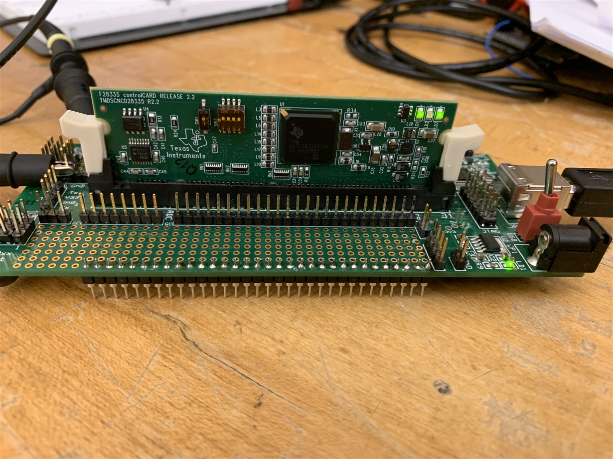
    2. I am using the F28335 right now. The docking station and the control card are shown in the attached photo.

    Thanks a lot for your time!

    Best,

    Jiangwei 

  • Jiangwei,

    Sorry to hear that. I have the setup as well. I’ll test it by Thursday and let you know what I find.

    Thanks,
    Sira
  • Jiangwei,


    I ran the test with the same hardware as you (my docking station is Docking-Stn USB-EMU [R3] and varied the frequency from the function generator from 1kHz to 9kHz, and it worked correctly, displaying the correct frequency in "freq" and also generating the correct plot in FFTReal_Magnitude. (you can graph this with the following properties - use a Single Time plot, 32-bit floating point, 257 values).


    This tells me there is either something wrong with your hardware, or with the way you are running the test, or looking at the measured values in CCS.

    Thanks,

    Sira

    28335-rfft_adc_rt-test.pdf


  • Jiangwei,

    Please click on "Verified Answer" if there's no more questions you have for me on this topic.

    Thanks!
    Sira
  • Dear Sira,

    Thanks for your reply! 

    I am thinking whether it's the way I see the measured values is wrong, I first tried to watch the value of the "freq" by directly type "freq" in the expression panel, but it showed that the value could not be found , so later I put the line "float32 freq;  " in front of main and made it a global variable, and added global variables or directly chose the "freq", and right clicked my mouse and chose add watch expressions, in this way, I got the 'freq" in the expression panel, but the value was not correct as I showed in the screen shot. Can you please tell me how you add the "freq" in the expression panel?

    Best,

    Jiangwei

  • Jiangwei,

    I didn't do anything special. I ran the code for sometime, then halted it. It typically stopped in main() inside the while(1) at the asm(" NOP");.

    Then I hovered over the freq variable inside main() and it showed the value there itself. I right-clicked on freq, clicked Add watch expression, entered freq and hit enter, and the value showed up correctly.

    Is the code stopping at the same location for you?

    Thanks,
    Sira
  • Jianwei,

    I sent a reply to you yesterday but looks like there was an issue with E2E at the time and so I don't see my post here.

    Anyway, I didn't do anything special to get freq to appear in the debug window. In fact, once you run the code for some time and halt it, it would usually halt in main() at asm(" NOP") and then I would hover over freq with my mouse and it would show the value.

    Note that CCS may also have some bugs wherein if you tried adding freq as an "expression" it may not work properly, whereas it may already be visible in the "Variables" tab.

    Please try these two approaches and let me know.

    Thanks,
    Sira
  • Jiangwei,

    Can you please provide an update on this? If your issue is resolved, please click on Answer Verified so that we can close the issue.

    Thanks,
    Sira
  • Dear Sira,

    Sorry for late reply, I 've been busy for finals these days, thanks a lot for your advice!

    Thanks,

    Jiangwei