This thread has been locked.

If you have a related question, please click the "Ask a related question" button in the top right corner. The newly created question will be automatically linked to this question.

CCS/TMDSHVMTRINSPIN: Unable to run motor

Part Number: TMDSHVMTRINSPIN
Other Parts Discussed in Thread: TMS320F28069, MOTORWARE, CCSTUDIO

Tool/software: Code Composer Studio

Hi All,

Good Afternoon to all of u,

I am using TMDSHVMTRINSPIN kit to run 3 hp PMSM without Load.

In this kit i do the following changes;-

1) Shorted J2,J3,J4,J5,J7,J8.

2) Connected Banana Cable from BS1 to BS5 (I am working on Ac)

3) Connected Power adapter to 15V Dc(Included in Kit)

4) Connected Ac Supply To the Kit

and remaining things remain same.

Motor -3HP PMSM Motor without Load.(is it ok or any problem with motor).

Problem Facing:-I included one doc for that.

When i connected motor with Kit through all power supply,motor have to run or it required any software requirement.

Software - CCS8.2 , Guicomposer/webapps

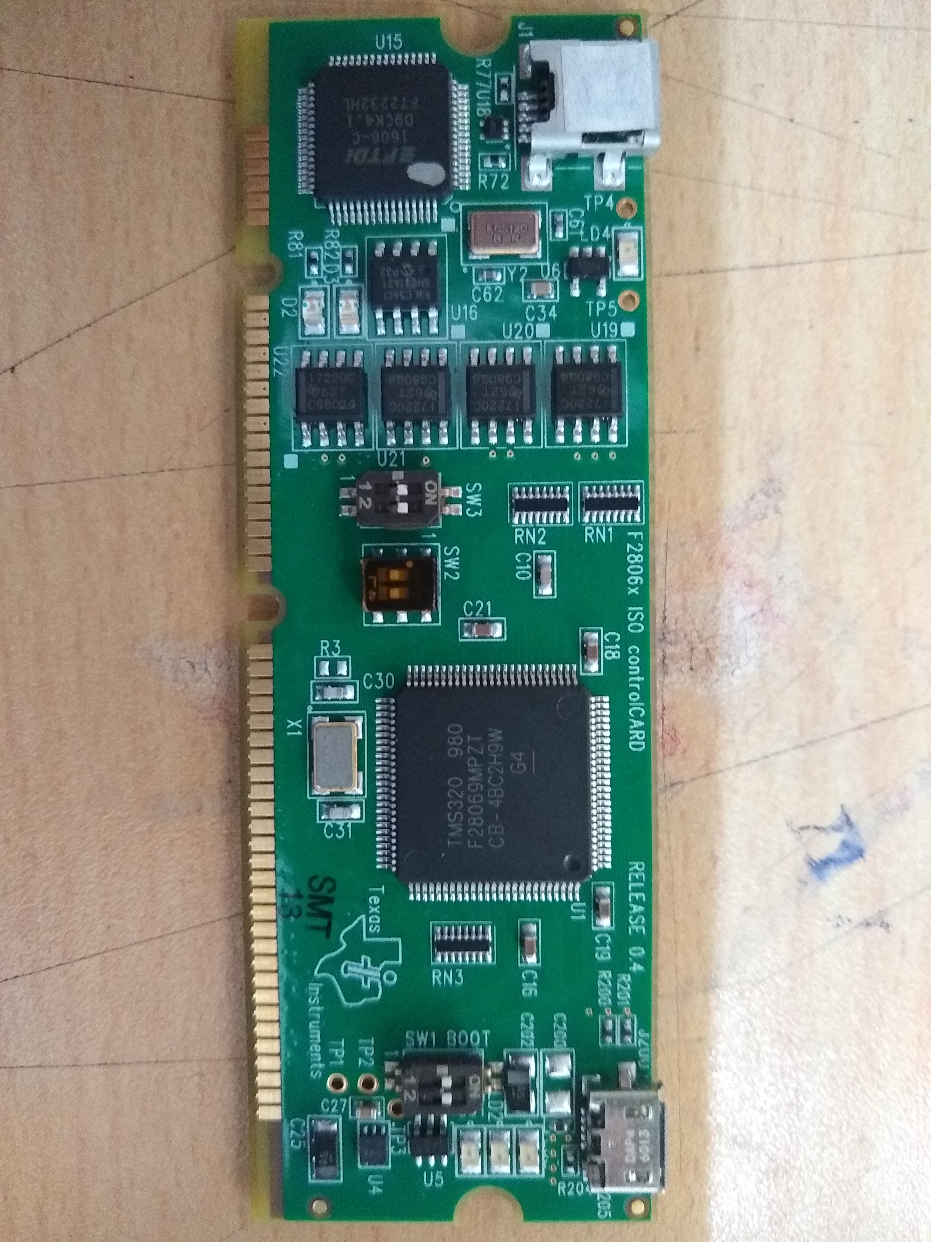
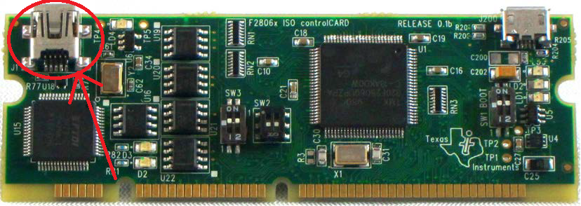
The Control Card contains TMS320F28069 micro controller.

Please suggest me with all proper method , how i do this thing.

Please help me.

Thank You

Shikhar Gupta

  • Looks like you are having an issue connecting to the debugger via JTAG. Are you providing the appropriate core voltage to the MCU? The documentation for the quick start guide should show the appropriate connections to make to provide power to the device: C:\ti\motorware\motorware_1_01_00_18\docs\boards\drive\hvkit_rev1p1\docs\qsg_hw_hvmtr_r1p1.pdf

    Sean
  •   Hi

    Good Morning Sir,

    I follow same paper that u provide me yesterday.

    But again it is not working.

    I am doing by Use of UART via [M3] on the HVMTRKIT baseboard.

    U can see the pic ....

    If u have any demo video plz provide..

    Please Clearly tell how to  run the motor by using your kit...

    I am confusing with the paper.. 

    Thank You

    Shikhar

  • It seems you're using the on-board XDS100, which is not appropriate for the ControlCARD you are using. Per this recommendation:

    Do NOT use the onboard XDS100 emulator when using a controlCARD with its own onbard emulation (ex: TMDSCNCDF28069MISO)
     populate jumper M3-J5 to disable emulator on HVKIT.

    You will need to populate M3-J5 jumper and instead program the device through the ControlCARD emulator.

    Sean
  • Good Morning Sir,
    Ok, i tried but it is showing same problem as i am facing early.
    Please suggest me appropriate and easy method by which i can see my motor is running.
    Humble request you u to please give me all details with appropriate method and any demo video please provide me.
  • Shikhar

    We do not have a demo video for setting up this development kit. The documentation that we have available for the HVKIT + F28069M is available in Motorware

    I assume you are using an AC input at [Main]-P1, correct? If so, you need to connect [Main]-BS1 and [Main]-BS5. I cannot verify this because your picture does not show where the banana cable is going to.

    You need to ensure that SW3-Position 1 is set to ON to allow for JTAG communications. Please ensure that [M3]-J5 is populated to disable the on-board JTAG debugger. Remove jumper [Main]-J9.

    Are the LEDs on the Control Card on or blinking to show that power is being supplied to the core?

    I would again ask that you review the documentation here: C:\ti\motorware\motorware_1_01_00_18\docs\boards\control\f2806x\docs
    and here: C:\ti\motorware\motorware_1_01_00_18\docs\boards\drive\hvkit_rev1p1\docs

    These are the most comprehensive guides available and should give full information on how to set up your kit. Documentation on the InstaSPIN Universal GUI is here: C:\ti\motorware\motorware_1_01_00_18\docs\guis\universal

    Sean
  •  Hi Sean,

    I am using AC power to provide the Kit and my using usb jtag emulator cable to connect Kit to my Pc.

    I put SW3 Switch 1 in ON sate and what about other Switch Sw1 and SW2 state?

    J9 not populate,j2,J3,J4,J5,J7,J8 are populated.

    Bs1 connected to Bs5.

    By Doing this, on control card two led Blinking one is green and other is Red.

    I am using InstaSPIN Universal Gui Software For F28069x.

    All these are correct according to the document u mention and by your suggestion.

    When i am not  popualting M3 J5 then in my PC it is showning Com Port and XDS 100 Class Port, that i attached in the pic.. otherwise when i populate M3 J5 then  it will not showing Com Port and XDS 100 Class Port in my Device manager.

    Again It  showing same error

    Restarting Program Model...

    Initializing target : C:\ti\guicomposer\eclipse\workspace\.metadata\.plugins\com.ti.binding.program\appConfig.ccxml

    Connecting target: Texas Instruments XDS100v2 USB Debug Probe/C28xx

    sun.org.mozilla.javascript.internal.WrappedException: Wrapped com.ti.ccstudio.scripting.environment.ScriptingException: Error connecting to the target: emulation failure occurred (<Unknown source>#14) in <Unknown source> at line number 14Restart Completed.

    I in my opinon when i populate M3 J5 my is not responding ...

    I already go the document u suggest me...i already done according to that..

    Please tell me what i have to do...

    Thank You

    Shikhar Gupta

  • Are you connecting to the debugger (mini USB) port on the control card instead of the USB port on the base board? You need to populate M3-J5 and connect to the control card debugger.

    Sean
  • Sean
    Thanks for your patience and response.
    I am connecting to debugger port on the Control Card.

    Error:- Restarting Program Model...
    Initializing target : C:\ti\guicomposer\eclipse\workspace\.metadata\.plugins\com.ti.binding.program\appConfig.ccxml
    Connecting target: Texas Instruments XDS100v2 USB Debug Probe/C28xx
    Loading program: null
    sun.org.mozilla.javascript.internal.WrappedException: Wrapped java.lang.NullPointerException (<Unknown source>#18) in <Unknown source> at line number 18Restart Completed.

    SW3 switch 1 in ON state.
    I am not connecting USB TAG Emulator.
    Thanks
    Shikhar
  • The default mode for SW2 should be ON-ON, can you confirm this?

    Please also ensure you are using the correct USB connection on the Control Card. I've marked the correct one in the picture below

    You can find a listing of which LEDs are reporting which status update in the Piccolo F28069M controlCARD Hardware Guide I linked earlier. Please check the LED listing and confirm the LED for JTAG logic is powered 

    Sean

  • If there's no additional question here, I will close this thread for now

    Sean