This thread has been locked.

If you have a related question, please click the "Ask a related question" button in the top right corner. The newly created question will be automatically linked to this question.

TMS320F28075: Abnormal behavior of IN_MODE configuration of ePWM

Part Number: TMS320F28075

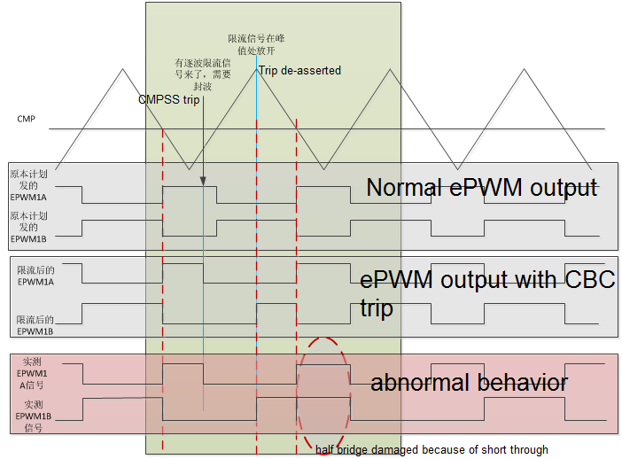
In our project, we encounter an 28075 ePWM wave problem in September. We grabbed the waveform to prove that power module(half-bridge) would be damaged because of short through.

Original Question Link: e2e.ti.com/.../2705829

1. Problem phenomenon

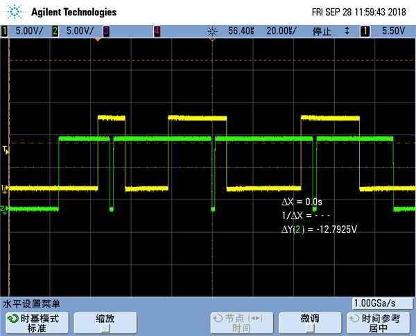
ePWM1A and ePWM1B were configured to complementary output. Ext SyncIn was connected to ePWM1A. CMPSS was used to trip the ePWM1 on a cycle-by-cycle basis. You can find the ePWM output waveforms we found. In the third waveform, ePWM1B cannot be cleared.

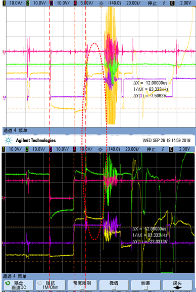
You can find their scope capture as follows. The purple waveform(CH3) in the first picture is ePWM1A, and the purple waveform(CH3) in the second picture is ePWM1B.

And there is no ePWM configuration again except the configuration(attached also) during initialization.

0827.Drv_PWM.cpp

6242.Drv_PWM.h

2. Some findings

Because of this problem, many of our machines are damaged. We did many experiments, and found some possible reasons.

2.1 Input sources configuration of ePWM

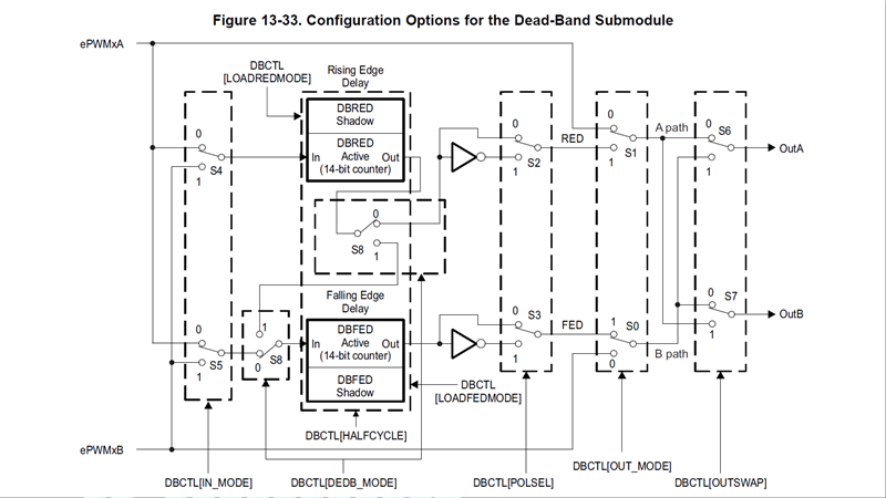
ePWMxA and ePWMxB are configured as two independent input sources in previous procedures based on f28075 datasheet. 

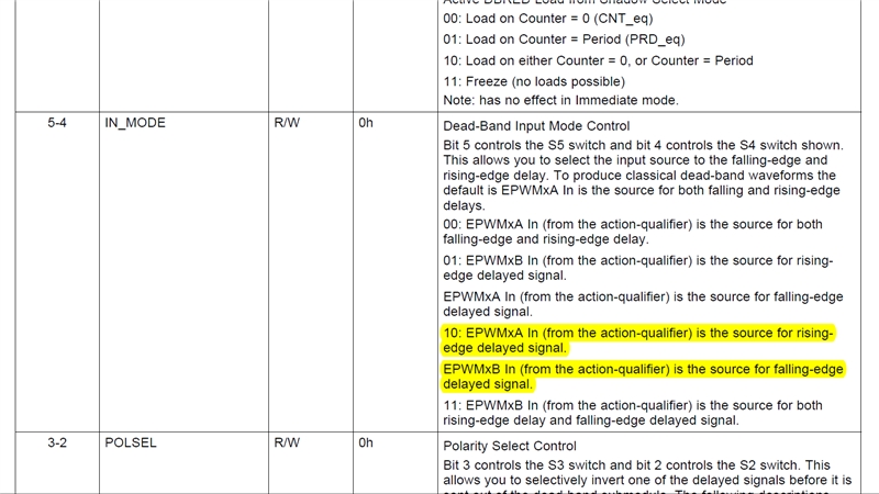
That is, EPwm1Regs.DBCTL.bit.IN_MODE = 0x2; 

10: EPWMxA In (from the action-qualifier) is the source for risingedgedelayed signal.EPWMxB In (from the action-qualifier) is the source for falling-edge delayed signal.

So we assign values to CMPA and CMPB respectively in the last part of CLA, but they are executed one by one.

Such as:

  EPwm1Regs.CMPA.bit.CMPA = INVThree_Output.fUpwmInv_A;
  EPwm1Regs.CMPB.bit.CMPB = INVThree_Output.fUpwmInv_A;

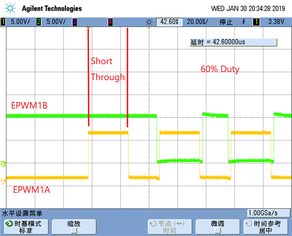
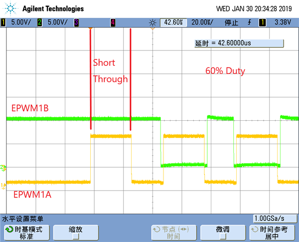
We conducted a simulation experiment, when CMPA executed the assignment statement, and CMPB did not execute the load statement, there will be a short through phenomenon. In the follow picture, CH1 is ePWM1A, and CH2 is ePWM1B.


Then, ePWMxA and ePWMxB are configured as only one source. 

That is, EPwm1Regs.DBCTL.bit.IN_MODE = 0x0; 

We repeated many experiments, and there was no abnormal or short through phenomenon. We have also confirmed that the CLA runtime meets the requirements.Due to project schedule, we took this modification measures. 

Over the past two months, hundreds of machines have been running for a long time without any problems.

2. Ext SyncIn single

In the five experiments, we all grabbed the synchronous signal, and found no abnormal signal.


Because the reason for this problem is not clear, we can not use 28075 chip for the next project. At present, we have no idea about this problem. Would you kindly help to check the root cause of this issue?


Thanks.

Regards,

Jetfan

  • Hi Jetfan,

    To me, setting DBCTL[IN_MODE] to 0 appears to be a valid configuration for your application. 

    You appear to want to use the value of 2 (instead of 0) based on your below comment:

    "ePWMxA and ePWMxB are configured as two independent input sources in previous procedures based on f28075 datasheet"

    What procedure in the Datasheet or TRM are you referring to?  I would like to review its validity and see if it applies to your situation.

    ===

    If you use IN_MODE as 2, I believe you should be able to resolve the issue that you are seeing by utilizing the Global Load features of the ePWM module.  You would set GLDCTL, GLDCTL2, and GLDCFG as necessary.  Doing so can enable CMPA and CMPB to be moved from their respective shadow registers to their active registers simultaneously.


    Thank you,
    Brett

  • Hi, Brett

    Thank you very much. I'm sorry for delay in replying to you. Please see the folwing reply.

    1. What procedure in the Datasheet or TRM are you referring to?

    Reply: Our problem program in September is configured as above. This configuration attachment is already included in the original text. You can download it for analysis. Epwm1, 2, 4, 5, 7 and 8 are PWM drivers of three-phase sinusoidal voltage. And, IN_MODE sample program was not found in the Datasheet.

    2. My main purpose is to find out why IN_MODE=2 went wrong. The GLDCTL, GLDCTL2, and GLDCFG registers you mentioned will be checked before I contact you again. Thank you for offering this idea.

    Regards

    Jetfan

  • Hi,

    If you are using IN_MODE=2 then the complementary operation of PWMA and PWMB is not guaranteed by default in the hardware, because there is dependency of software updating the CMPA and CMPB registers separately in this case. If, for some reason, one of the statements is not executed - this could be due to code being interrupted or a Sync operation changing the sequence of events etc. So, your configuration and operation has to ensure that no such events abnormalities occur which could break the complementary operation.
    That is your issue in using IN_MODE=0?
  • Hi, Subahmanya

    Thank you very much. You're right. Using IN_MODE=2 can't guarantee hardware complementarity, so we changed the configuration IN_MODE==0, and the results are also feasible.

    For the speculation reasons,interrupted or a Sync operation,none of our experiments can prove it.interrupted. When ePWM is abnormal, interrupt time is enough, and no synchronization operation occurred. So we want to find out exactly what caused it, interrupted, Sync operation, CMPSS, or other factors. Many of the underlying mechanisms are unknown to us. 

    Regards

    Jetfan

  • Hi,

    It's difficult to say what exactly caused the behavior. But you can narrow it down by doing some experiments.
    1. To rule out if interrupt related issues are causing this problem, you can try the following. Disable all other interrupts in the system other than the PWM interrupt used for updating the CMPA/B registers. Also, you can try to slow down the ISR to make sure that there latency is not causing any problem.
    2. To rule out sync issues, simply disable SYNC operation and try to run the same test.
    Similarly, you can try ruling out the cause for misbehavior one after another.
    From a quick look without actually running the full system, if I have to guess, I suspect it's probably something to do with the Sync operation. 

  • Hi, Subrahmanya

    First of all, thank you very much for Providing these two ideas. I will do experiments to prove it.

    1. Interrupt related issues  

    Our device is parallel system of UPS, it requires a lot of changing settings to changing settings, so I haven't done this experiment yet. I plan  to reduce interrupt time by reducing interrupt programs firstly. We have done a comparative experiment before.

    'IN_MODE=2' problem program which cause abnormal behavior of PWM is a debugging program, it run about 10 more lines of algorithm code than 'IN_MODE=2' normal program. However, it will cause the IGBT damage. These additional code do not operate register configuration, but it caused the algorithm oscillate, and then triggered CMPSS.

    2. Sync issues

    I have done the experiment to disable SYNC operation today. As a result, IGBT is still damaged, and the damage is consistent with previous experiments. In the iive experiments we did in October, we all grabbed the synchronous signal, and found no abnormal signal. You can check the PWM configuration changes in my experiment today. Please see the following attachment.

    Drv_PWM_1-5.cpp

    Thanks.

    Regards,

    Jetfan

  • Hi,

    If disabling SYNC has no effect on the system behavior then very likely Sync is not the cause.
    Also, I would suggest to try to replicate this issue on an  independent hardware like ControlCard or so you can avoid burning the IGBTs.
    Debug and root causing the issue would also be simpler. Let us know the result of you Interrput related experiment.

  • Hi,

    Did you get a chance to debug further?
  • Hi Subrahmanya

    I'm sorry the experiment was delayed for several days due to other urgent work. 

    I did a comparative experiment on the simulation control board. PWM did not appear abnormal for the original CLA code program and the program which reduce CLA code. The simulation board can't collect the drastically changing voltage and current. So I plan to do the experiment on the actual equipment tomorrow.

    At the same time, I looked at the datasheet of 28075,  and found a problem.

    There's a description in the chapter 13.6.4 AQCTLA and AQCTLB Shadow Mode Operations.

    ————————————————————————————

    NOTE: Shadow to Active Load of Action Qualifier Output A/B Control Register [AQCTLA & AQCTLB] on CMPA = 0 or CMPB = 0 boundary If the Counter-Compare A Register (CMPA) or Counter-Compare B Register (CMPB) is set to a value of 0 and the action qualifier action on AQCTLA and AQCTLB is configured to occur in the same instant as a shadow to active load (that is, CMPA=0 and AQCTLA shadow to active load on TBCTR=0 using AQCTLR register LDAQAMODE and LDAQAMODE bits), then both events enter contention and it is recommended to use a Non-Zero Counter-Compare when using Shadow to Active Load of Action Qualifier Output A/B Control Register on TBCTR = 0 boundary.

    ————————————————————————————

    CMPSS function is configured in our program,and CMPA and CMPB may be 0. There will be CMPSS trip before a short through phenomenon occured in our test. You can see the waveform in the description of the original question. Triggering CMPSS and CMPA(CMPB)==0 at same time, does it cause PWM abnormal behavior? I'll do experiment to confirm it, too.

    Regards

    Jetfan

  • Hi,

    If the below conditions are all true -
    1. You are using Shadow to active load for AQCTLA/B registers - which means in your application you are dynamically changing the values of AQCTLA/B.
    2. The Shadow-to-active load event chosen for AQCTLA/B is Counter-equals-zero.
    3. CMPA/B values are actively controlling the PWM (Ex: set PWMA on CMPA match event etc.)
    Then you should avoid using CMPA/B values as zero to avoid contention mentioned above.
    It didn't seem like you were changing the AQCTLA/B values dynamically in the application.
    If so, you need to beware of the note above and it could lead to unexpected behavior.
  • Hi,Subrahmanya

    In these days, we have done a lot of experiments to verify it. At present, we have the following conclusions.

    1. CLA runtime is normal. We have done experiments to reduce the running time of CLA and increase the running time of CLA, respectively. Experiments can prove that PWM did not appear abnormal for the original CLA code program. 

    2.Assigning values to CMPA and CMPB is normal. We have done experiments to capture CMPA and CMPB assignment anomalies, but the result is OK. So, our guess 'CMPA executed the assignment statement, and CMPB did not execute the load statement'is wrong. At the same time, our program does not actually assign CMPA and CMPB 0.

    3.CMPSS and SYNC operations is OK. 

    4.Vulnerabilities exist in'IN_MODE==2'mode of DSP chips. We conducted a simulation experiment, PWM frequency is 20KHZ, and the following CMPA and CMPB assignment statements are executed interleaved at 40KHZ frequency.

     if(Pub_Cla2Cpu.INVdebug_1 > 0)   //The Positive half-part of a sinusoidal wave
     {
      //Case 1    Pub_Cla2Cpu.INVdebug_1=1
            EPwm1Regs.AQCSFRC.bit.CSFA = AQC_NO_ACTION;
            EPwm1Regs.AQCSFRC.bit.CSFB = AQC_NO_ACTION;

            EPwm2Regs.AQCSFRC.bit.CSFA = FORCE_LOW;
            EPwm2Regs.AQCSFRC.bit.CSFB = FORCE_LOW;

            EPwm1Regs.CMPA.bit.CMPA = Pub_Cla2Cpu.INVdebug_2;
            EPwm1Regs.CMPB.bit.CMPB = Pub_Cla2Cpu.INVdebug_2;
     }
     else   //The negative half-part of a sinusoidal wave
     {  

    //Case 2 Pub_Cla2Cpu.INVdebug_1=2
            EPwm1Regs.AQCSFRC.bit.CSFA = FORCE_LOW;
            EPwm1Regs.AQCSFRC.bit.CSFB = FORCE_LOW;

            EPwm2Regs.AQCSFRC.bit.CSFA = AQC_NO_ACTION;
            EPwm2Regs.AQCSFRC.bit.CSFB = AQC_NO_ACTION;

            EPwm2Regs.CMPA.bit.CMPA = Pub_Cla2Cpu.INVdebug_2;
            EPwm2Regs.CMPB.bit.CMPB = Pub_Cla2Cpu.INVdebug_2;
     }

    In the above code, Pub_Cla2Cpu.INVdebug_1 transforms between 1 and 0 at 40KHZ frequency, so case1 part and case 2 part is executed at 40KHZ frequency. After running for a period of time, Pub_Cla2Cpu.INVdebug_1 is always equal to 1, so CASE1 part is always double executed. The duty cycle of PWM is 60%, IN_MODE==2, CMPSS and SYNC operations are disbaled.

    In this process, EPWM1 will appear abnormal phenomena. In the follow picture, CH1 is ePWM1A, and CH2 is ePWM1B.

    Because of the algorithm oscillation, the original program will cause CASE1 and CASE2 to be executed by high frequency switching. The above simulation results are consistent with our previous experimental results.

    To sum up, we think this problem belongs to the reason of DSP chip. When EPWM is configured as 'IN_MODE==2'mode, the performance is not entirely consistent for EPWM1A and EPWM1B,  maybe due to the delay of the underlying circuit of DSP, etc.

    We think the reason of this problem has been found.

    Thank you very much. It would be better if you could prove it.

  • Hi,Subrahmanya

    In these days, we have done a lot of experiments to verify it. At present, we have the following conclusions.

    1. CLA runtime is normal. We have done experiments to reduce the running time of CLA and increase the running time of CLA, respectively. Experiments can prove that PWM did not appear abnormal for the original CLA code program. 

    2.Assigning values to CMPA and CMPB is normal. We have done experiments to capture CMPA and CMPB assignment anomalies, but the result is OK. So, our guess 'CMPA executed the assignment statement, and CMPB did not execute the load statement'is wrong. At the same time, our program does not actually assign CMPA and CMPB 0.

    3.CMPSS and SYNC operations are OK. 

    4.Vulnerabilities exist in 'IN_MODE==2'mode of DSP chips. Our PWM switching frequency is 20KHZ, and the control algorithm frequency is 40KHZ. We conducted a simulation experiment, the abnormal phenomena are proved. 

     if(Pub_Cla2Cpu.INVdebug_1 > 0)   //the positive half-part of sine wave
     {
     // Case 2 Pub_Cla2Cpu.INVdebug_1 = 1;
      
         EPwm1Regs.AQCSFRC.bit.CSFA = AQC_NO_ACTION;
         EPwm1Regs.AQCSFRC.bit.CSFB = AQC_NO_ACTION;
         EPwm2Regs.AQCSFRC.bit.CSFA = FORCE_LOW;
         EPwm2Regs.AQCSFRC.bit.CSFB = FORCE_LOW;
         EPwm1Regs.CMPA.bit.CMPA = Pub_Cla2Cpu.INVdebug_2;
         EPwm1Regs.CMPB.bit.CMPB = Pub_Cla2Cpu.INVdebug_2;
     }
     else  //the negative half-part of sine wave
     {
     // Case 2 Pub_Cla2Cpu.INVdebug_1 = 0;
      
         EPwm1Regs.AQCSFRC.bit.CSFA = FORCE_LOW;
         EPwm1Regs.AQCSFRC.bit.CSFB = FORCE_LOW;
         EPwm2Regs.AQCSFRC.bit.CSFA = AQC_NO_ACTION;
         EPwm2Regs.AQCSFRC.bit.CSFB = AQC_NO_ACTION;
         EPwm2Regs.CMPA.bit.CMPA = Pub_Cla2Cpu.INVdebug_2;
         EPwm2Regs.CMPB.bit.CMPB = Pub_Cla2Cpu.INVdebug_2;
     }

    In the above program, Pub_Cla2Cpu.INVdebug_1 exchanges  between 0 and 1 at 40KHZ frequencies, so Case 1 part and Case 2 part  are executed at 40KHZ frequencies. The EPwm is configured as 'IN_MODE==2' mode, and CMPSS and SYNC operations are disabled, PWM duty is 60%.

    When Pub_Cla2Cpu.INVdebug_1 is suddenly changed to constant 1, CASE1 part is executed consistently. At this time, the PWM wave will appear abnormal. In the follow picture, CH1 is ePWM1A, and CH2 is ePWM1B.

    Because of the algorithm oscillation, the original code CASE1 and CASE2 will be executed at high frequencies. The above simulation results are consistent with our previous experimental results.

    We think the cause of this problem has been found. The performance of EPWM1A and EPWMB is not consistent at high frequencies in 'IN_MODE==2' mode, may be due to delay of underlying circuit.

    Thank you very much. It wil be better if you can prove it. 

    Regards,

    Jetfan


  • Hi,

    Thanks a lot for all the experiments and data you've gathered.
    Were you able to replicate the issue down to an independent setup - like a controlCard or so?
    If so, please share the configuration so that we can replicate the issue at our end. 


    With the IN_MODE==2 and the way your application is controlling the PWM generation - it's difficult to ascertain the source of the problem.
    One of the anomalies i've noticed is that you are using CSFA with immediate load mode.

    EPwm1Regs.AQSFRC.bit.RLDCSF = 3; //The active register load immediately

     This is purely dependent on the s/w timing of when this write occurs. Where as other events controlling the PWM (like the compare match events are based off of the shadow to active loading). Can you try using EPwm1Regs.AQSFRC.bit.RLDCSF = 0 ?

  • Hi,

    Did you get a chance t try the above?
    It would really help debug faster and close this, if you can replicate the failing condition on controlCard setup using a test case.
    Now that you are able to simulate the condition, it should be easy to narrow down the failing condition.

  • Hi Subrahmanya

    I'm very sorry that I can't reply to your information in time, because of the Chinese Spring Festival holiday. Today I will do the above experiment to  confirm "EPwm1Regs.AQSFRC.bit.RLDCSF = 3; " issue. 

    Thank you very much.

    Regards

    Jetfan

  • No problem - i just wanted to know if you are waiting for any additional information. Also, please try to have a test that we can replicate here so that the issue can be closed quickly.
  • Hi Subrahmanya

    I've done a comparative experiment. 

    "EPwm1Regs.AQSFRC.bit.RLDCSF = 0" experiments show that no PWM abnormal phenomena will occur, no abnormalities were found in at least 100 experiments.

    However, "EPwm1Regs.AQSFRC.bit.RLDCSF = 3" experiments will occur abnormal PWM phenomena about 5 times.


    I don't understand what's going wrong on here.


    Thanks.

    Jetfan

  • Hi,

    That's great - we could identify the issue. With RLDCSF=3 the PWM state is directly dependent on your s/w timing.
    Where as when you use shadow load you've a better control on the timing of the events and less dependency of s/w updating at a certain time.
    That's the reason I asked you to try RLDCSF=0. It's always good to use shadow mode, unless you've total control on the s/w timing and updates to the PWM.
    Let me know if you've any other issues or need any clarifications. If not, we can consider this thread closed.

  • Hi, Subahmanya

    My understanding is as follows. Please check it. Thank you.

    "RLDCSF=3" means  PWM state dependent on the update time in my code.  Because of my program oscillation, PWM has an update exception problem. This is consistent with the experimental waveform.

    My understanding is that both EPWM1A and EPWM1B should be abnormal. However, why is EPWM1B abnormal and EPWM1A normal? I also need to look at the datasheet to understand why.

    regards

    Jetfan

  • Hi,

    Your understanding is correct - with RLDCSF=3" , PWM is completely dependent on the s/w updates in the code.
    Regarding EPWM1A and EPWM1B difference - it's difficult for me to comment unless I'm able to understand exact condition.
    My guess would be, i think i mentioned this earlier as well, that something in your software is causing a discontinuity or unexpected behavior (sync, interrupt etc.).
    I can't think of anything else causing such behavior - given that you are able to replicate in simulations, you should have more insight into the exact condition under which this behavior is seen. 

  • Hi,

    Did you get a chance to debug this further? Can we close this thread now?