This thread has been locked.

If you have a related question, please click the "Ask a related question" button in the top right corner. The newly created question will be automatically linked to this question.

TMS320F28035: The ADC SOC11 result is unstable

Part Number: TMS320F28035

Hi,

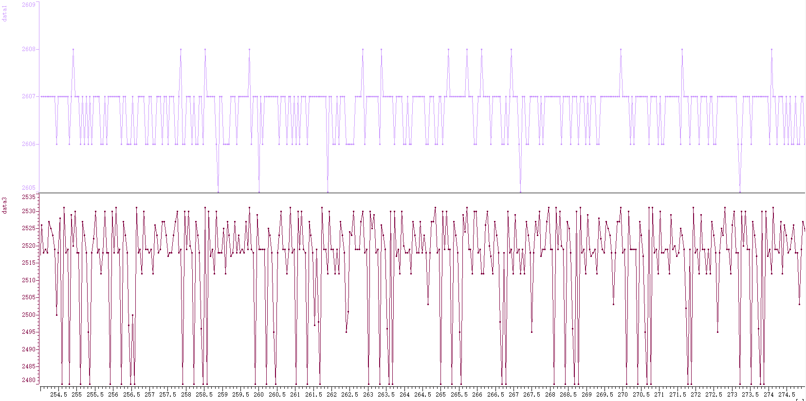
As above picture, SCO11 ADC convert result has ~60 fluctuation. It can not be resolved even enlarge ACQPS time.

It only has this problem on SOC11, which can't be reproduced if detect SOC11 input on other SOC.

Attach ADC code here, is there any suggestion for us trouble shooting in further? Thanks a lot.

ADC setting.txt
Fullscreen
1
2
3
4
5
6
7
8
9
10
11
12
13
14
15
16
17
18
19
20
21
22
23
24
25
26
27
28
29
30
31
32
33
34
35
36
37
38
39
40
41
42
43
44
45
46
47
48
49
50
51
52
53
54
55
56
57
58
59
60
61
62
63
64
65
66
67
void AdcInit(void)
{
InitAdc();
EALLOW;
// 1.?????????????,?????????
AdcRegs.ADCSAMPLEMODE.all = 0;
// 2.?????????
AdcRegs.ADCCTL1.bit.TEMPCONV = 1;
// 3.??SOCx??????,[??]????RESULT_XXX???
AdcRegs.ADCSOC0CTL.bit.CHSEL = CH_PFC_IT1; // ????????,?PWM??
AdcRegs.ADCSOC1CTL.bit.CHSEL = CH_PFC_IT1; // CH_PFC_IN_IAC;
AdcRegs.ADCSOC2CTL.bit.CHSEL = CH_PFC_IT1; // CH_PFC_IN_IAC
AdcRegs.ADCSOC3CTL.bit.CHSEL = CH_PFC_IT2; // CH_PFC_IN_IAC;
AdcRegs.ADCSOC4CTL.bit.CHSEL = CH_PFC_IT2; // CH_PFC_IN_IAC;
AdcRegs.ADCSOC5CTL.bit.CHSEL = CH_PFC_VAC_L;
AdcRegs.ADCSOC6CTL.bit.CHSEL = CH_PFC_VAC_L; //result_6
AdcRegs.ADCSOC7CTL.bit.CHSEL = CH_PFC_VAC_N;
AdcRegs.ADCSOC8CTL.bit.CHSEL = CH_PFC_VAC_N; //result_8
AdcRegs.ADCSOC9CTL.bit.CHSEL = CH_VBULK; // ?????????
AdcRegs.ADCSOC10CTL.bit.CHSEL = CH_VBULK; //result_10
AdcRegs.ADCSOC11CTL.bit.CHSEL = CH_NTC_AMB;
AdcRegs.ADCSOC12CTL.bit.CHSEL = CH_NTC_LLC;
AdcRegs.ADCSOC13CTL.bit.CHSEL = CH_PFC_IN_IAC;
AdcRegs.ADCSOC14CTL.bit.CHSEL = CH_LLC_DRV_UDC;
AdcRegs.ADCSOC15CTL.bit.CHSEL = CH_NTC_PFC; //pfc??
// 4. ??SOCx??? //debug: ????????????
AdcRegs.ADCSOC0CTL.bit.TRIGSEL = ADCTRIG_EPWM1_SOCA; //PFC?????
AdcRegs.ADCSOC1CTL.bit.TRIGSEL = ADCTRIG_EPWM1_SOCA; //IT1
AdcRegs.ADCSOC2CTL.bit.TRIGSEL = ADCTRIG_EPWM1_SOCA; //IT1
AdcRegs.ADCSOC3CTL.bit.TRIGSEL = ADCTRIG_EPWM2_SOCA; //IT2
AdcRegs.ADCSOC4CTL.bit.TRIGSEL = ADCTRIG_EPWM2_SOCA; //IT2
AdcRegs.ADCSOC5CTL.bit.TRIGSEL = ADCTRIG_EPWM1_SOCA;
AdcRegs.ADCSOC6CTL.bit.TRIGSEL = ADCTRIG_EPWM1_SOCA;
AdcRegs.ADCSOC7CTL.bit.TRIGSEL = ADCTRIG_EPWM2_SOCA;
AdcRegs.ADCSOC8CTL.bit.TRIGSEL = ADCTRIG_EPWM2_SOCA; //?LLC??pwm??
AdcRegs.ADCSOC9CTL.bit.TRIGSEL = ADCTRIG_EPWM1_SOCA; //?LLC??pwm??
AdcRegs.ADCSOC10CTL.bit.TRIGSEL = ADCTRIG_EPWM1_SOCA;
AdcRegs.ADCSOC11CTL.bit.TRIGSEL = ADCTRIG_CPU_TINT0;
AdcRegs.ADCSOC12CTL.bit.TRIGSEL = ADCTRIG_CPU_TINT0;
AdcRegs.ADCSOC13CTL.bit.TRIGSEL = ADCTRIG_CPU_TINT0;
AdcRegs.ADCSOC14CTL.bit.TRIGSEL = ADCTRIG_CPU_TINT0;
AdcRegs.ADCSOC15CTL.bit.TRIGSEL = ADCTRIG_CPU_TINT0;
// 5. ??????(???? = ACQPS_Value + 1)
#define ACQPS_Value 8
AdcRegs.ADCSOC0CTL.bit.ACQPS = ACQPS_Value;
AdcRegs.ADCSOC1CTL.bit.ACQPS = ACQPS_Value;
AdcRegs.ADCSOC2CTL.bit.ACQPS = ACQPS_Value;
AdcRegs.ADCSOC3CTL.bit.ACQPS = ACQPS_Value;
AdcRegs.ADCSOC4CTL.bit.ACQPS = ACQPS_Value;
AdcRegs.ADCSOC5CTL.bit.ACQPS = ACQPS_Value;
AdcRegs.ADCSOC6CTL.bit.ACQPS = ACQPS_Value;
AdcRegs.ADCSOC7CTL.bit.ACQPS = ACQPS_Value;
AdcRegs.ADCSOC8CTL.bit.ACQPS = ACQPS_Value;
AdcRegs.ADCSOC9CTL.bit.ACQPS = ACQPS_Value;
AdcRegs.ADCSOC10CTL.bit.ACQPS = ACQPS_Value;
AdcRegs.ADCSOC11CTL.bit.ACQPS = ACQPS_Value;
AdcRegs.ADCSOC12CTL.bit.ACQPS = ACQPS_Value;
AdcRegs.ADCSOC13CTL.bit.ACQPS = ACQPS_Value;
AdcRegs.ADCSOC14CTL.bit.ACQPS = ACQPS_Value;
AdcRegs.ADCSOC15CTL.bit.ACQPS = ACQPS_Value;
#undef ACQPS_Value
// 6. ?????????:??0 & 1 : ?????????,??????,?????PWM??
XXXXXXXXXXXXXXXXXXXXXXXXXXXXXXXXXXXXXXXXXXXXXXXXXX

  • Daniel,

    Can you confirm that the ADC Advisories from the Errata are handled correctly?  Can you also confirm that CH_NTC_AMB can be converted properly when using another SOC?

    If there is still trouble after the workarounds have been implemented, it will help to know the mapping of channels to SOCs as well as the signal conditioning used for the problem channel.  For example, I do not know what channel is used for CH_NTC_AMB and what its electrical characteristics are.

    -Tommy

  • Hi tlee,

    Thanks for your advice. We are working on checking code according Errata.

    By the way, here is SOC 11 sampling circuit, to detect NTC temperature. ADC reference is 2.5V.

    As below picture, both SOC11 and SOC15 are used to detect NTC temperature. Purple is SOC15 ADC conversion result, brown is SOC11.

    After switch SOC11 and SOC15 input, Purple is SOC11 ADC conversion result, brown is SOC15 result.

    As you see, the ADC jump value on SOC15 is usually below 10, but it's up to 50-70 at SOC11.

  • Daniel,

    So it sounds like the problem is tracking with the circuit. Correct?

    Can you let me know which ADC channel is connected to the circuit? The ADC channels are identified as A0-A7 and B0-B7.

    How frequently is the circuit sampled? Is there any detectable disturbance on the circuit if monitored with an oscilloscope?

    -Tommy
  • tlee,

    In default, SOC11 is connected to B7, SOC15 is connected to B3.
    100usec sampling interval.
  • Daniel,

    Is there a circuitry difference between the NTC on B7 and B3? Is B7 connected to NTC_AMB (not shown in schematic snippet) and B3 connected to NTC_PFC (shown in schematic snippet)?

    Does slowing down the sampling interval improve the stability?

    Is A7 used for other conversions? Whenever A7 is sampled, the B7 S/H capacitor will also be connected to its pin so this can affect the recovery time of slow bandwidth signals.

    -Tommy
  • Hi Tommy,

    “Is there a circuitry difference between the NTC on B7 and B3? Is B7 connected to NTC_AMB (not shown in schematic snippet) and B3 connected to NTC_PFC (shown in schematic snippet)?”

    ---- You are right, B7 connected to NTC_AMB as the below shown, and B3 connected to NTC_PFC shown as above.

    "Is A7 used for other conversions? Whenever A7 is sampled, the B7 S/H capacitor will also be connected to its pin so this can affect the recovery time of slow bandwidth signals."

    ---- A7 is sampled in 65kHz frequency to SOC4

    "Does slowing down the sampling interval improve the stability?"

    ---- Customer will debug these few days.

    Thanks!

    - Rayna Wang

  • Hi Tommy,

    Update some testing results form customer, hope you could give some suggestions, thanks!

    1. Change SOC triggers
    1.1 Change the trigger of SOC11 from ADCTRIG_CPU_TINT0(10kHz) to ADCTRIG_EPWM1_SOCA(65kHz, same trigger with SOC10, S0C9), the ADCResult11 is correct, however the ADCResult12 fluctuation range is 58 LSB.
    1.2 Change the trigger of SOC10 from ADCTRIG_EPWM1_SOCA to ADCTRIG_CPU_TINT0, the ADCResult11 is correct, while the range of ADCResult10 fluctuation is 82 LSB.

    2. Oversample by matching SOC10, SOC11 and SOC12 with AMB NTC(B7), Keep the original trigger sequence unchanged. There is only ADCResult11 is abnormal, which fluctuation range is 48 LSB.

    The above testing results show that the ADCResult of first SOC channel triggered by ADCTRIG_CPU_TINT0 will be abnormal.

    Could you give some suggestions on this issue? Thanks!

    - Rayna Wang
  • Rayna,

    There does appear to be a difference in NTC circuitry between AMB vs LLC and PFC. That might account for some differences in behavior.

    With respect to the first sample, my original reply to Daniel was a request to confirm that all ADC advisories are handled correctly. There is an ADC first sample advisory in the errata that might explain the observations.

    -Tommy
  • Hi Tommy,

    Thanks for reminding, I have find the ADC advisory about this issue, is this the below one?

    - Rayna Wang

  • Yes, that is the Advisory that I was referencing.
  • Hi Tommy,

    Thanks for the support!

    - Rayna Wang