This thread has been locked.
If you have a related question, please click the "Ask a related question" button in the top right corner. The newly created question will be automatically linked to this question.
Good afternoon,
I´m having some troubles to use the ADC inputs of my TMS320F28377S, I'm working from Simulink. I have read the helps of Matlab, but I have troubles identifying the relation of the ports and to understand it,
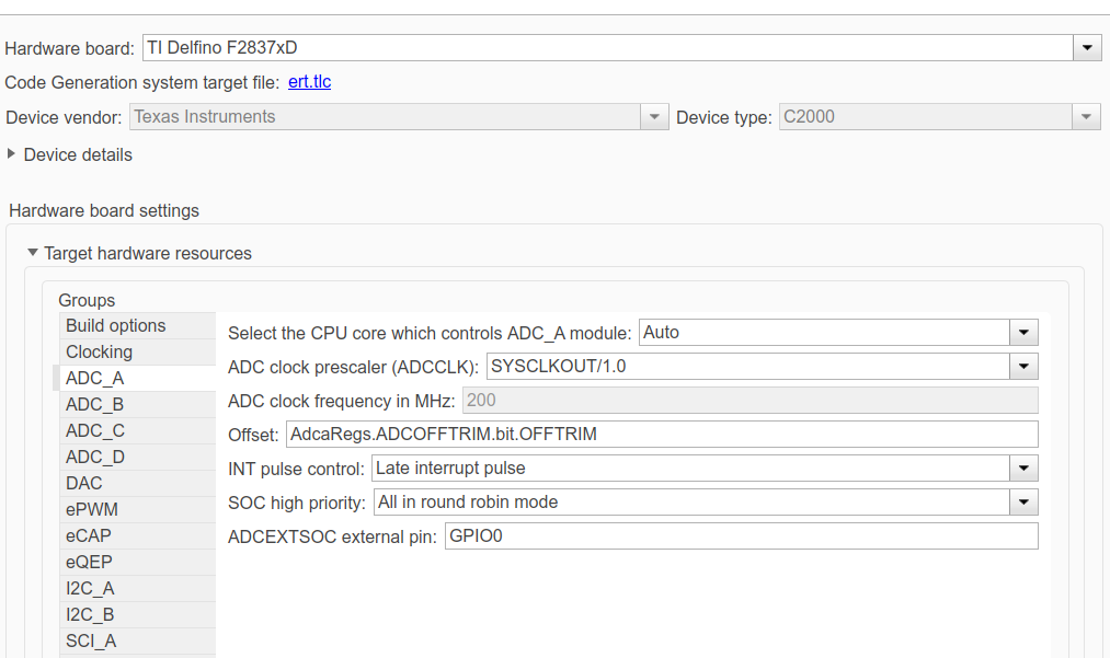
in the help they explain that it´s necesary to configure the clocks: https://la.mathworks.com/help/supportpkg/texasinstrumentsc2000/ug/configuring-acquisition-window-width-for-adc-blocks.html
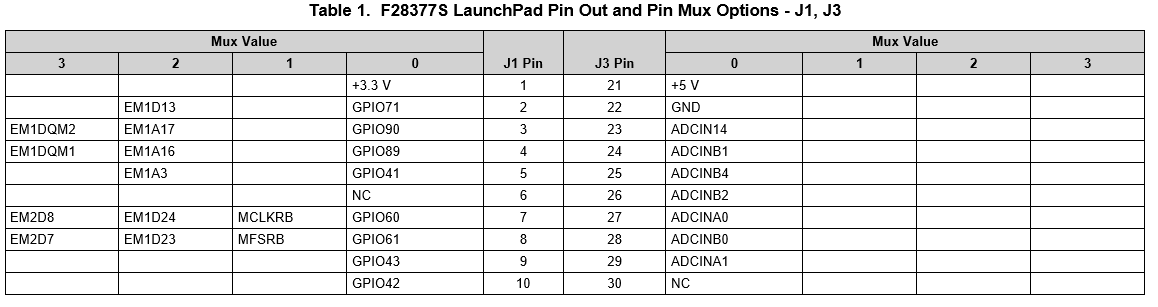
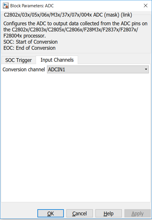
but in the window that appears for my micro, appears a compleatelly different information, I open the help system proposed in matworks but the input channel only saids ADCIN1 but my card have A and B inputs, I configure the parameters in the other page of the interface but i connect a constant signal in the stablished pin and don't obtain any signal in the scope in simulink
Thanks for your help,
I will try again with those settings
Best regards, Juan Antonio
Hi,
Please note, the input channel lists channel numbers 1-16 - i.e ADCIN0 - ADCIN15 on 'Input Channels' Tab.
And it lists the 'ADC module' under the SOC Trigger Tab. You will have to select the appropriate module for your ADC from this drop down. Like you said you have ADC module B, you may select the same.
Also, please select F2837xS as the device from 'hardware board' drop down.
Do ensure to test the reading once in CCS for the given ADC pin which is being used in Simulink.
Contact Mathworks technical support if issue persists.