This thread has been locked.

If you have a related question, please click the "Ask a related question" button in the top right corner. The newly created question will be automatically linked to this question.

TMS320F28069: TMS320F28069 How to use serial_flash_programmer ??

Part Number: TMS320F28069
Other Parts Discussed in Thread: C2000WARE

We first verified that the sci hardware state is OK by communicating with the pc through the "scia example".

 Communication picture.

1. "C: \ ti \ c2000 \ C2000Ware_1_00_06_00 \ device_support \ f2806x \ examples \ c28 \ f28069_sci_flash_kernel"
I imported the example in ccs and compiled it.

2. Copy the file "f28069_sci_flash_kernel.out" to the folder "c: test".

2.1 I did not download the "f28069_sci_flash_kernel.out" file to 28069. The reason is that "serial_flash_programmer" believes that it will download.

3. I copied "HEX2000.exe" file in "C: \ ti \ ccsv6 \ tools \ compiler \ ti-cgt-c2000_6.4.6 \ bin" folder to folder "c: test"

4. Open the Windows command line and enter the "c: test" directory.
"hex2000.exe -boot -sci8 -a -o f28069_sci_flash_kernel.txt f28069_sci_flash_kernel.out"

5. The file "f28069_sci_flash_kernel.txt" was created (I never opened it. When I open it I sometimes see that Windows adds strange numbers.)

6. "C: \ ti \ c2000 \ C2000Ware_1_00_06_00 \ device_support \ f2806x \ examples \ c28 \ timed_led_blink"
I imported the example in ccs and compiled it.
I downloaded the program to the emulator and confirmed that the led is toggling.

7. Copy the file "Example_2806xLEDBlink.out" to the folder "c: test".

8. Open the Windows command line and go to the "c: test" directory and run the following command:
"hex2000.exe -boot -sci8 -a -o Example_2806xLEDBlink.txt Example_2806xLEDBlink.out"

9. "Example_2806xLEDBlink.txt" file was created (I never opened it. When I opened it, sometimes I saw that Windows added strange numbers.)

10. I removed the emulator from my board.Currently only SCIA communication and power are connected.

11. gpio34 - Set (3.3v pull-up)
gpio-37 - non set (gnd pull-down)

12. Power off the "28069".

13. Turn on the power of "28069".

14. "led blink" does not work.
Therefore, it was considered to be in "sci boot mode".

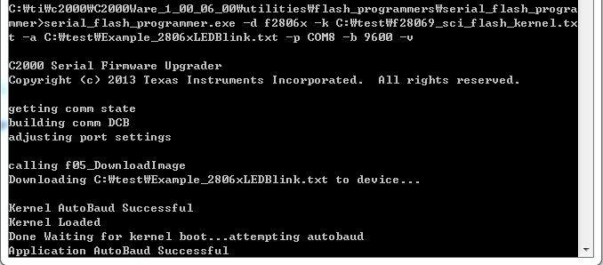
15. Proceed as shown in the following picture.

16. "Downloading C: \ test \ Example_2806xLEDBlink.txt to device ..."
There is no response after 20 minutes.

So please let me know if I made a mistake.
I can not solve for a month.

  • Hi,

    Please use the -v option for verbose printing. If it is downloading the kernel, the characters should be echoed in the terminal.

    It appears the autobaud lock and SCI communication may not be working. Please make sure you are using the same GPIO pins which the SCi bootloader is using.

    sal
  • Thanks for the quick answer.

    But the answer did not solve my problem.

    1. You can see that the last picture already contains the "-v" option.However, after the last picture, there is no character after "Downloading C: \ test \ Example_2806xLEDBlink.txt to device ...".

    2. It is set to "gpio28 (SCIA_RX)" and "gpio29 (SCIA_TX)" and you can see "0x61" sent to Hyper Terminal in "Sci_A_ucRX" as shown in the first picture.
    And when I put "0x62" in "SciaRegs.SCITXBUF", I confirmed that English character "b" is displayed on Hyper Terminal of PC.

    There is more question.

    3. After downloading "out file" of "f28069_sci_flash_kernel" to "internal flash ROM" of "DSP", should I proceed from the first question of the first question?
    Is it right to think like the question "2.1"?

    4. If you look at the SPRABV4B document
    "if necessary. It then waits for an 'a' or 'a' from the host in order to perform an autobaud lock with the host. "
    There is this content.
    Is this automatically sent to the Host (PC) from the DSP?
    If so, is the Cmd window visible?
    If not, how does "autobaud lock" work?

    5.In the first question

    11. gpio34 - Set (3.3v pull-up)
    gpio-37 - non set (gnd pull-down)

    12. Power off the "28069".

    13. Turn on the power of "28069".

    14. "led blink" does not work.
    Therefore, it was considered to be in "sci boot mode".
    Is there any way to verify that the DSP goes into SCI Boot mode when I go through the sequence? (I have an oscilloscope, so I can see all the pins of the DSP.)

    Oh, my God, I did not connect the ground during the experiment.

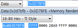
    The characters are printed as follows: Is the program downloaded to the internal flash ROM?

    Like the picture, the application project is now programmed in the RAM area as "RAM.cmd". Should I use "ROM.cmd"?

    I downloaded the internal flash ROM program using "Rom.cmd".

    Thank you for answer.

    I would like to download the program to the internal ROM area only from the external serial communication line (tx, rx, gnd).

    However, as an extraordinary question, "serial_flash_programmer" should initially set "gpio34" and "gpio37".

    Therefore, when rebooting the program, "gpio34" and "gpio37" must be set again.
    I want to download the program without modifying "gpio".
    Is there any other way?

  • Hi,

    Your latest post is incomprehensible.

    It looks like you got it working. You cannot program ROM. That is why it is Read Only Memory.

    If you want to perform a device firmware update without modifying the boot control pins, then you need to have some way to signal your system/device to go branch to the SCI bootloader in ROM. You can make a function call into the ROM bootloader if you add the Boot ROM symbol library into your project.

    You can see other E2E forum posts for help with this.

    Hope this helps,
    sal
  • Thank you for answer.

    With the gpio setting, sci_boot mode has been enabled to download programs to the internal flash ROM area.

    But I am now
    1. fix the setting to gpio34 - high, gpio37 - high (get mode), and no Emulator.
    2. The software calls the sci_boot function
    3. I want to download the program to the internal Flash ROM area.

    http://e2e.ti.com/support/microcontrollers/c2000/f/171/p/754532/2789202?tisearch=e2e-sitesearch&keymatch=boot_rom#2789202

    You said you only need to add a ".lib file".
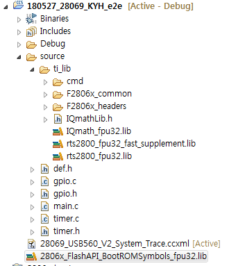
    However, when you look at the next picture, an error is generated.

    Therefore,

    C: \ ti \ c2000 \ C2000Ware_1_00_06_00 \ libraries \ boot_rom \ f2806x \ v1_1 \ rom_sources \ source

    I need to add .c and .h files to my project.
    Is this my idea?

    If so, are there any e2e posts or datasheets I can recommend?

    I would appreciate it if you send us a link.

  • In your main,

    extern the protype of the SCI boot function.

    Also, do not include both .libs. Only include the .lib which you need. If you are compiling your project with fpu enabled, then use the fpu version.

    sal
  • There is some heplful information in this thread.

    e2e.ti.com/.../758414

    sal
  • I am using fpu.
    therefore
    C:\ti\c2000\C2000Ware_1_00_06_00\libraries\boot_rom\f2806x\v1_1\rom_symbol_libs\Flash_API\2806x_FlashAPI_BootROMSymbols_fpu32.lib
    Added.

    However, the sci_boot () function still can not be called.

    Attach my main.c.

    #include "DSP28x_Project.h"
    
    extern MemCopy();
    extern Uint32 SCI_Boot(void);
    
    void (*entry)();
    
    WORD wCntMain = 0;
    WORD test_boot_sci=0;
    
    unsigned long boot_addr = 0x003fe74a;
    
    void main(void) {
    
    // //
    // // GPIO and SCI are still setup from Sci_Boot()
    // // Setup sysctl and pll
    // //
    // DisableDog();
    // IntOsc1Sel();
    // InitPll(DSP28_PLLCR,DSP28_DIVSEL);
    //
    // DELAY_US(100);
    // return SCI_Boot();
    
    	InitSysCtrl();
    	MemCopy(&RamfuncsLoadStart, &RamfuncsLoadEnd, &RamfuncsRunStart);
    	InitFlash();
    
    	DINT;
    	InitPieCtrl();
    	IER = 0x0000;
    	IFR = 0x0000;
    
    	InitPieVectTable();
    	InitCpuTimers();
    
    	Init_Gpio();
    	Timer_Init();
    
    	EINT;
    	/* Enable Global interrupt INTM */
    	ERTM;
    	/* Enable Global realtime interrupt DBGM */
    	for(;;)
    	{
    		wCntMain++;
    		if( test_boot_sci==1 )
    		{
    			//%%%%%%%%%%%%%%%%%%%%%%%%%%%%%%%%%%%%%%%%%%%%%%%%%%%%%%%%
    			//Prepare For SCI BootLoading
    			//%%%%%%%%%%%%%%%%%%%%%%%%%%%%%%%%%%%%%%%%%%%%%%%%%%%%%%%%
    			EALLOW;
    			DINT;
    			EDIS;
    			PieCtrlRegs.PIECTRL.bit.ENPIE = 0; // Disable the PIE
    			DisableDog(); // Disable the watchdog
    			IntOsc1Sel();
    			InitPll(DSP28_PLLCR,DSP28_DIVSEL);
    			EALLOW;
    			entry = (void(*)())(boot_addr);
    			entry();
    
    //			boot_addr=Sci_Boot();
    //			((void (*)(void))boot_addr)();
    
    		}
    	}
    
    }
    
    
    //===========================================================================
    // No more.
    //===========================================================================


    #include "DSP28x_Project.h"

    extern MemCopy();
    extern Uint32 SCI_Boot(void);

    void (*entry)();

    WORD wCntMain = 0;
    WORD test_boot_sci=0;

    unsigned long boot_addr = 0x003fe74a;

    void main(void) {

    // //
    // // GPIO and SCI are still setup from Sci_Boot()
    // // Setup sysctl and pll
    // //
    // DisableDog();
    // IntOsc1Sel();
    // InitPll(DSP28_PLLCR,DSP28_DIVSEL);
    //
    // DELAY_US(100);
    // return SCI_Boot();

    InitSysCtrl();
    MemCopy(&RamfuncsLoadStart, &RamfuncsLoadEnd, &RamfuncsRunStart);
    InitFlash();

    DINT;
    InitPieCtrl();
    IER = 0x0000;
    IFR = 0x0000;

    InitPieVectTable();
    InitCpuTimers();

    Init_Gpio();
    Timer_Init();

    EINT;
    /* Enable Global interrupt INTM */
    ERTM;
    /* Enable Global realtime interrupt DBGM */
    for(;;)
    {
    wCntMain++;
    if( test_boot_sci==1 )
    {
    //%%%%%%%%%%%%%%%%%%%%%%%%%%%%%%%%%%%%%%%%%%%%%%%%%%%%%%%%
    //Prepare For SCI BootLoading
    //%%%%%%%%%%%%%%%%%%%%%%%%%%%%%%%%%%%%%%%%%%%%%%%%%%%%%%%%
    EALLOW;
    DINT;
    EDIS;
    PieCtrlRegs.PIECTRL.bit.ENPIE = 0; // Disable the PIE
    DisableDog(); // Disable the watchdog
    IntOsc1Sel();
    InitPll(DSP28_PLLCR,DSP28_DIVSEL);
    EALLOW;
    entry = (void(*)())(boot_addr);
    entry();

    // boot_addr=Sci_Boot();
    // ((void (*)(void))boot_addr)();

    }
    }

    }

    1. I do not think this should add only lib. Is that correct?

    2. And when I open the lib that I added with Notepad, there is no information about sci_boot (). therefore
    C:\ti\c2000\C2000Ware_1_00_06_00\libraries\flash_api\f2806x\lib\2806x_BootROM_API_TABLE_Symbols_fpu32.lib
    I think it is right to add.
    Is that correct?

  • The prototype must be defined correctly.

    Uint32 SCI_Boot(Uint32 BootMode)

    So please do this:

    extern Uint32 SCI_Boot(Uint32 BootMode);

    And in your program call this function appropriately.

    You can see the prototype and the code in C2000Ware. We provide all of this for you.

    sal
  • I think you are mistaken now.

    I do not use f2837xd,F2837xs,F2807x,f2833x,f28004x series DSP.

    I am using F28069.

    See the source of SCI_Boot.c in the library of C2000.
    It is located in the following directory:

    C: \ ti \ c2000 \ C2000Ware_1_00_06_00 \ libraries \ boot_rom \ f2806x \ v1_1 \ rom_sources \ source

    The Uint32 SCI_Boot (Uint32 BootMode) prototype you mentioned
    It exists only in the directory of F2837x.

    It is located in the following directory:

    C: \ ti \ c2000 \ C2000Ware_1_00_06_00 \ libraries \ boot_rom \ f2837xs \ revB \ rom_sources \ F2837x_bootROM \ cpu01-bootROM \ source

    Please check the directory of your computer and give me the answer.

  • You are correct. I mentioned the wrong API.

    If you extern the API in the file in which you are making the function call and also include the .lib in your CCS project, the compiler and linker will build the project properly.

    Please let me know the specific issue you are seeing.

    sal
  • I think I do not need to call the SCI_Boot () function.

    Because "serial_flash_programmer" uses "28069_sci_flash_kernel.txt" file, I believe "serial_flash_programmer" will call "SCI_Boot ()" function.

    Just set it to sci boot mode.

    The first method was gpio setting.

    I would like to set the "sci boot mode" to software.

  • The serial flash programmer is a PC application which communicates with the device.

    If I understand correctly, you want to run the bootloader from your application. In this case, just call SCI_Boot() from your application to begin to execute the SCI bootloader in ROM.
  • Another way was to call the sci_boot () function.

    The method looks like the following main.c.

    ------------------------------------------main.c------------------------------------

    #include "DSP28x_Project.h"

    extern MemCopy();
    extern Uint32 SCI_Boot();

    WORD wCntMain = 0;
    WORD test_boot_sci=0;

    unsigned long sci_boot_addr = 0x003ff699;
    unsigned long init_boot_addr = 0x003ff760;
    unsigned long select_boot_addr = 0x003ff459;
    #define Device_cal (void (*)(void))0x3D7C80
    Uint32 (*entry)();

    Uint32 main(void) {

    InitSysCtrl();
    MemCopy(&RamfuncsLoadStart, &RamfuncsLoadEnd, &RamfuncsRunStart);
    InitFlash();

    DINT;
    InitPieCtrl();
    IER = 0x0000;
    IFR = 0x0000;

    InitPieVectTable();
    InitCpuTimers();

    Init_Gpio();
    Timer_Init();

    EINT;
    /* Enable Global interrupt INTM */
    ERTM;
    /* Enable Global realtime interrupt DBGM */

    EALLOW;

    // Watchdog Service
    ServiceDog();

    // Init two locations used by the flash API with 0x0000
    Flash_CPUScaleFactor = 0;
    Flash_CallbackPtr = 0;
    EDIS;

    // Read the password locations - this will unlock the
    // CSM only if the passwords are erased. Otherwise it
    // will not have an effect.
    CsmPwl.PSWD0;
    CsmPwl.PSWD1;
    CsmPwl.PSWD2;
    CsmPwl.PSWD3;
    CsmPwl.PSWD4;
    CsmPwl.PSWD5;
    CsmPwl.PSWD6;
    CsmPwl.PSWD7;

    DisableDog();
    LED1_ON;
    LED2_ON;
    LED3_ON;
    LED4_ON;
    LED5_ON;
    LED6_ON;
    LED7_ON;
    LED8_ON;

    IntOsc1Sel();
    InitPll(DSP28_PLLCR,DSP28_DIVSEL);

    DELAY_US(100);
    entry = (Uint32(*)())(sci_boot_addr);
    return entry();
    }

    ------------------------------------------main.c------------------------------------

    I am in C:\ti\c2000\C2000Ware_1_00_06_00\libraries\boot_rom\f2806x\v1_1\rom_sources\Release directory Refer to the "TMS320x2806x_boot_rom.map" file
    I have found that the address of the "sci_boot()" function is 0x003ff699.

    However, in the cmd window, the same text as the next window is displayed.

    The dsp state at this time is the "SCIA_GetWordData()" function
       "while (SciaRegs.SCIRXST.bit.RXRDY! = 1) {}".

    I think the "SelectMode()" or "Init_Boot" function should be called first, rather than just a simple "sci_boot()" function call.

    Is that correct?

  • Uint32 SCI_Boot() initializes the SCI sufficiently. You should be able to call the function as you are doing.

    It appears the serial flash programmer may be sending data to the device which is perhaps too frequent and a byte is getting lost.

    1) Can you try running the boot loader from stand alone mode to see if you can get it working? By this I mean please boot the device to SCI boot mode and use the serial flash programmer.

    2) Try lowering the baudrate to see if this helps.

    sal
  • 1) It works. ( I could confirm txt file is normal )

    2) 9600, 1200, 75 I have set three baud rate, but it has no effect.

    3) I have confirmed that can not get out of "CopyData()" through breakpoints.

    I have confirmed that the contents of the "CopyData()" function in the following two "Shared_Boot.c" are different.

    1. C:\ti\c2000\C2000Ware_1_00_06_00\libraries\boot_rom\f2806x\v1_1\rom_sources\source\Shared_Boot.c

    ---------------------------------1---CopyData()---1---------------------------------

    //-----------------------------------------------------
    
    void CopyData()
    {
    
       struct HEADER {
         Uint16 BlockSize;
         Uint32 DestAddr;
       } BlockHeader;
    
       Uint16 wordData;
       Uint16 i;
    
       // Get the size in words of the first block
       BlockHeader.BlockSize = (*GetWordData)();
    
       // While the block size is > 0 copy the data
       // to the DestAddr.  There is no error checking
       // as it is assumed the DestAddr is a valid
       // memory location
    
       while(BlockHeader.BlockSize != (Uint16)0x0000)
       {
          BlockHeader.DestAddr = GetLongData();
          for(i = 1; i <= BlockHeader.BlockSize; i++)
          {
              wordData = (*GetWordData)();
              *(Uint16 *)BlockHeader.DestAddr++ = wordData;
          }
    
          // Get the size of the next block
          BlockHeader.BlockSize = (*GetWordData)();
       }
       return;
    }

    ---------------------------------1---CopyData()---1---------------------------------

    2. C:\ti\c2000\C2000Ware_1_00_06_00\device_support\f2806x\examples\c28\f28069_sci_flash_kernel\Shared_Boot.c

    ---------------------------------2---CopyData()---2---------------------------------

    void
    CopyData(void)
    {
        struct HEADER
        {
            Uint16 BlockSize;
            Uint32 DestAddr;
            Uint32 ProgBuffAddr;
        } BlockHeader;
    
        Uint16 wordData;
        Uint16 status;
        Uint16 i,j;
    
        //
        // Make sure code security is disabled
        //
        CsmUnlock();
    
        EALLOW;
        Flash_CPUScaleFactor = SCALE_FACTOR;
        Flash_CallbackPtr = NULL;
        EDIS;
    
        status = Flash_Erase((SECTORA | SECTORB | SECTORC | SECTORD), 
                             &FlashStatus);
        if(status != STATUS_SUCCESS)
        {
            //
            // Return
            //
            return;
        }
    
        //
        // After Flash Erase, send the checksum to PC program.
        //
        SendCheckSum();
        
        //
        // Get the size in words of the first block
        //
        BlockHeader.BlockSize = (*GetOnlyWordData)();
    
        //
        // While the block size is > 0 copy the data to the DestAddr.  There is no 
        // error checking as it is assumed the DestAddr is a valid memory location
        //
        while(BlockHeader.BlockSize != (Uint16)0x0000)
        {
            if(BlockHeader.BlockSize > PROG_BUFFER_LENGTH)
            {
                //
                // Block is to big to fit into our buffer so we must program it in 
                // chunks
                //
                BlockHeader.DestAddr = GetLongData();
                
                //
                // Program as many full buffers as possible
                //
                for(j = 0; j < (BlockHeader.BlockSize / PROG_BUFFER_LENGTH); j++)
                {
                    BlockHeader.ProgBuffAddr = (Uint32)progBuf;
                    for(i = 1; i <= PROG_BUFFER_LENGTH; i++)
                    {
                        wordData = (*GetOnlyWordData)();
                        *(Uint16 *)BlockHeader.ProgBuffAddr++ = wordData;
                    }
                    status = Flash_Program((Uint16 *) BlockHeader.DestAddr, 
                             (Uint16 *)progBuf, PROG_BUFFER_LENGTH, &FlashStatus);
                    
                    if(status != STATUS_SUCCESS)
                    {
                        return ;
                    }
                    BlockHeader.DestAddr += PROG_BUFFER_LENGTH;
                    
                    //
                    // After Flash program, send the checksum to PC program.
                    //
                    SendCheckSum();
                }
                
                //
                // Program the leftovers
                //
                BlockHeader.ProgBuffAddr = (Uint32)progBuf;
                for(i = 1; i <= (BlockHeader.BlockSize % PROG_BUFFER_LENGTH); i++)
                {
                    wordData = (*GetOnlyWordData)();
                    *(Uint16 *)BlockHeader.ProgBuffAddr++ = wordData;
                }
                status = Flash_Program((Uint16 *) BlockHeader.DestAddr, 
                         (Uint16 *)progBuf, (BlockHeader.BlockSize % 
                         PROG_BUFFER_LENGTH), &FlashStatus);
                         
                if(status != STATUS_SUCCESS)
                {
                    return ;
                }
                
                //
                // After Flash program, send the checksum to PC program.
                //
                SendCheckSum();
            }
                
            else
            {
                //
                // Block will fit into our buffer so we'll program it all at 
                // once
                //
                BlockHeader.DestAddr = GetLongData();
                BlockHeader.ProgBuffAddr = (Uint32)progBuf;
                for(i = 1; i <= BlockHeader.BlockSize; i++)
                {
                    wordData = (*GetOnlyWordData)();
                    *(Uint16 *)BlockHeader.ProgBuffAddr++ = wordData;
                }
                status = Flash_Program((Uint16 *) BlockHeader.DestAddr, 
                         (Uint16 *)progBuf, BlockHeader.BlockSize, &FlashStatus);
                if(status != STATUS_SUCCESS)
                {
                    return ;
                }
                
                //
                // After Flash program, send the checksum to PC program.
                //
                SendCheckSum();
            }
    
            //
            // Get the size of the next block
            //
            BlockHeader.BlockSize = (*GetOnlyWordData)();
        }
        return;
    }

    ---------------------------------2---CopyData()---2---------------------------------

    I think the contents of the second Shared_Boot.c are correct. Is that correct?

  • Both are correct.

    The boot loader uses echo back communication to ensure correctness. It receives one byte and echoes back that byte to the host to check for data integrity. It then writes the data to RAM.

    The kernel uses a checksum for data integrity.

    Regards,
    sal
  • Long time no see.


    I will ignore the other posts I have posted and focus on this post.

    Stand-Alone Boot Mode is not possible because "SciBoot.asm" is located in Ram area.
    So, my position is the Get Mode: Flash mode of emulation boot mode.

    I saw  post and created a "SciBoot.asm" file and included it in the project.

    https://e2e.ti.com/support/microcontrollers/c2000/f/171/p/246637/1515835?tisearch=e2e-sitesearch&keymatch=%20user:180128#pi320995=2

    As he puts "SciBoot.asm" in the "RAML0" area
    The remaining applications are located in the "FLASHE" area.

    MEMORY
    {
    PAGE 0 :   /* Program Memory */
               /* Memory (RAM/FLASH/OTP) blocks can be moved to PAGE1 for data allocation */
       RAML0       : origin = 0x008000, length = 0x000800     /* on-chip RAM block L0 */
       RAML1       : origin = 0x008800, length = 0x000400     /* on-chip RAM block L1 */
       OTP         : origin = 0x3D7800, length = 0x000400     /* on-chip OTP */
    
       FLASHH      : origin = 0x3D8000, length = 0x004000     /* on-chip FLASH */
       FLASHG      : origin = 0x3DC000, length = 0x004000     /* on-chip FLASH */
       FLASHF      : origin = 0x3E0000, length = 0x004000     /* on-chip FLASH */
       FLASHE      : origin = 0x3E4000, length = 0x004000     /* on-chip FLASH */   
       FLASHD      : origin = 0x3E8000, length = 0x004000     /* on-chip FLASH */
       FLASHC      : origin = 0x3EC000, length = 0x004000     /* on-chip FLASH */
       FLASHA      : origin = 0x3F4000, length = 0x003F80     /* on-chip FLASH */
       CSM_RSVD    : origin = 0x3F7F80, length = 0x000076     /* Part of FLASHA.  Program with all 0x0000 when CSM is in use. */
       BEGIN       : origin = 0x3F7FF6, length = 0x000002     /* Part of FLASHA.  Used for "boot to Flash" bootloader mode. */
       CSM_PWL_P0  : origin = 0x3F7FF8, length = 0x000008     /* Part of FLASHA.  CSM password locations in FLASHA */
    
       FPUTABLES   : origin = 0x3FD860, length = 0x0006A0	  /* FPU Tables in Boot ROM */
       IQTABLES    : origin = 0x3FDF00, length = 0x000B50     /* IQ Math Tables in Boot ROM */
       IQTABLES2   : origin = 0x3FEA50, length = 0x00008C     /* IQ Math Tables in Boot ROM */
       IQTABLES3   : origin = 0x3FEADC, length = 0x0000AA	  /* IQ Math Tables in Boot ROM */
    
       ROM         : origin = 0x3FF3B0, length = 0x000C10     /* Boot ROM */
       RESET       : origin = 0x3FFFC0, length = 0x000002     /* part of boot ROM  */
       VECTORS     : origin = 0x3FFFC2, length = 0x00003E     /* part of boot ROM  */
    
    PAGE 1 :   /* Data Memory */
               /* Memory (RAM/FLASH/OTP) blocks can be moved to PAGE0 for program allocation */
               /* Registers remain on PAGE1                                                  */
    
       BOOT_RSVD   : origin = 0x000000, length = 0x000050     /* Part of M0, BOOT rom will use this for stack */
       RAMM0       : origin = 0x000050, length = 0x0003B0     /* on-chip RAM block M0 */
       RAMM1       : origin = 0x000400, length = 0x000400     /* on-chip RAM block M1 */
       RAML2       : origin = 0x008C00, length = 0x000400     /* on-chip RAM block L2 */
       RAML3       : origin = 0x009000, length = 0x001000	  /* on-chip RAM block L3 */
       RAML4       : origin = 0x00A000, length = 0x002000     /* on-chip RAM block L4 */
       RAML5       : origin = 0x00C000, length = 0x002000     /* on-chip RAM block L5 */
       RAML6       : origin = 0x00E000, length = 0x002000     /* on-chip RAM block L6 */
       RAML7       : origin = 0x010000, length = 0x002000     /* on-chip RAM block L7 */
       RAML8       : origin = 0x012000, length = 0x002000     /* on-chip RAM block L8 */
       USB_RAM     : origin = 0x040000, length = 0x000800     /* USB RAM		  */   
       FLASHB      : origin = 0x3F0000, length = 0x004000     /* on-chip FLASH */     
    }
    
    /* Allocate sections to memory blocks.
       Note:
             codestart user defined section in DSP28_CodeStartBranch.asm used to redirect code
                       execution when booting to flash
             ramfuncs  user defined section to store functions that will be copied from Flash into RAM
    */
    
    
    SECTIONS
    {
    
       /* Allocate program areas: */
       .cinit              : > FLASHE,     PAGE = 0
       .pinit              : > FLASHE,     PAGE = 0
       .text               : > FLASHE,     PAGE = 0
       .InitBoot           : > FLASHE,     PAGE = 0
       codestart           : > BEGIN,      PAGE = 0
       ramfuncs            : LOAD = FLASHD,
                             RUN = RAML1,
                             LOAD_START(_RamfuncsLoadStart),
                             LOAD_END(_RamfuncsLoadEnd),
                             RUN_START(_RamfuncsRunStart),
    						 LOAD_SIZE(_RamfuncsLoadSize),
                             PAGE = 0
    
       csmpasswds          : > CSM_PWL_P0, PAGE = 0
       csm_rsvd            : > CSM_RSVD,   PAGE = 0
    
       /* Allocate uninitalized data sections: */
       .stack              : > RAMM0,      PAGE = 1
       .ebss               : > RAML2|RAML3,      PAGE = 1
       .esysmem            : > RAML2,      PAGE = 1
    
       /* Initalized sections to go in Flash */
       /* For SDFlash to program these, they must be allocated to page 0 */
       .econst             : > FLASHE,     PAGE = 0
       .switch             : > FLASHE,     PAGE = 0
    
       /* Allocate IQ math areas: */
       IQmath              : > FLASHE,     PAGE = 0            /* Math Code */
       IQmathTables        : > IQTABLES,   PAGE = 0, TYPE = NOLOAD
       securebootfuncs     : > RAML0,     PAGE = 0
       /* Allocate FPU math areas: */
       FPUmathTables       : > FPUTABLES,  PAGE = 0, TYPE = NOLOAD
       
       DLOG				   : > RAML7,	   PAGE = 1
    
       DMARAML5	           : > RAML5,      PAGE = 1
       DMARAML6	           : > RAML6,      PAGE = 1
       DMARAML7	           : > RAML7,      PAGE = 1
       DMARAML8	           : > RAML8,      PAGE = 1   
    
      /* Uncomment the section below if calling the IQNexp() or IQexp()
          functions from the IQMath.lib library in order to utilize the
          relevant IQ Math table in Boot ROM (This saves space and Boot ROM
          is 1 wait-state). If this section is not uncommented, IQmathTables2
          will be loaded into other memory (SARAM, Flash, etc.) and will take
          up space, but 0 wait-state is possible.
       */
       /*
       IQmathTables2    : > IQTABLES2, PAGE = 0, TYPE = NOLOAD
       {
    
                  IQmath.lib<IQNexpTable.obj> (IQmathTablesRam)
    
       }
       */
        /* Uncomment the section below if calling the IQNasin() or IQasin()
           functions from the IQMath.lib library in order to utilize the
           relevant IQ Math table in Boot ROM (This saves space and Boot ROM
           is 1 wait-state). If this section is not uncommented, IQmathTables2
           will be loaded into other memory (SARAM, Flash, etc.) and will take
           up space, but 0 wait-state is possible.
        */
        /*
        IQmathTables3    : > IQTABLES3, PAGE = 0, TYPE = NOLOAD
        {
    
                   IQmath.lib<IQNasinTable.obj> (IQmathTablesRam)
    
        }
        */
    
       /* .reset is a standard section used by the compiler.  It contains the */
       /* the address of the start of _c_int00 for C Code.   /*
       /* When using the boot ROM this section and the CPU vector */
       /* table is not needed.  Thus the default type is set here to  */
       /* DSECT  */
       .reset              : > RESET,      PAGE = 0, TYPE = DSECT
       vectors             : > VECTORS,    PAGE = 0, TYPE = DSECT
    
    }
    
    /*
    //===========================================================================
    // End of file.
    //===========================================================================
    */


    The result of running "serial_flash_programmer" as "Visual Studio"
    "f05_DownloadImage.cpp" file is stuck in the same place as the picture.


    Where is the "ReadFile" function reading something and why not reading it?

    Thank you

    Kim

  • The host is waiting to receive data back. This may be occurring because some data has been lost by either the device or the host.

    I suggest using VS and CCS to debug this. Run the host and the device using the IDE and debuggers to help yourself debug this issue.

    Thank you,
    sal