This thread has been locked.

If you have a related question, please click the "Ask a related question" button in the top right corner. The newly created question will be automatically linked to this question.

TMS320F28069 : TMS320F28069 How do I enter serial boot mode?

Part Number: TMS320F28069

DSP : TMS320F28069

CCS : 6.1.2.00015

DEBUGGER : USB560 V2 System Trace ( Blackhawk )

Thank you in advance.


I succeeded in entering the sci boot mode through the gpio setting.

Please see the picture below.
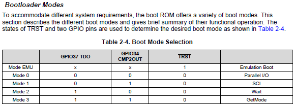

However, I want to enter sci boot mode in my application program, not the gpio setting.


How do I enter boot mode in software?

  • Hi,

          The boot mode is always controlled by gpio setting. You can't enter the boot mode from application program.

          What is your use case and the flow ?

    Regards

    Baskaran

  • Are you still facing this issue, if so please provide more details.

    Regards

    Baskaran

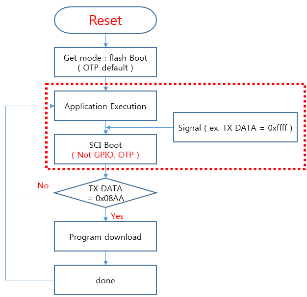
  • I want to implement the functionality of a red dotted box.

  • I am not sure if this approach will work but you can give a try.

    Call "EntryAddr = SCI_Boot()" from your application code. Then jump to EntryAddr (function pointer).
  • 	entry = (Uint32(*)())(0x003f4abd);
    	entry();
    

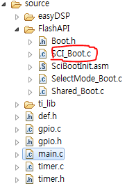
    1. I added the SCI_Boot.c file to my project.
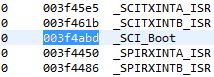
    2. According to the .map file, the address value of the Sci_Boot () function is 0x003f4abd.
    3. So I coded like this.

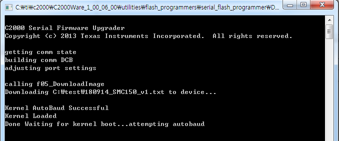
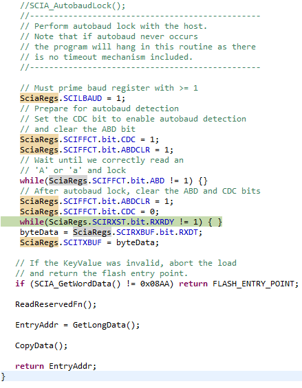
    serial_flash_programmers Execution result is stopped at the following part.

    As a result of many experiments, I think that I need to copy and modify the contents embedded in the DSP.
    When the Dsp is first reset, the contents of Initboot are executed and the boot mode is selected according to the contents of the selectmode function.
    A simple call to the sci_boot () function is useless.

  • can you load your application program to ccs and see what is the behavior.
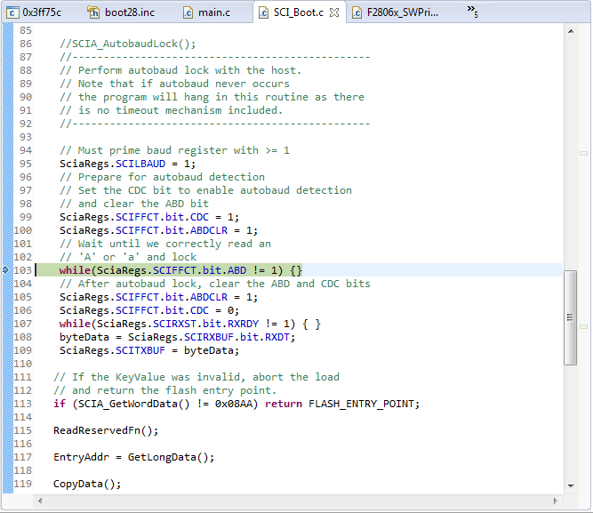
  • 1. After downloading the source, the dsp is waiting in the same position as the picture below.

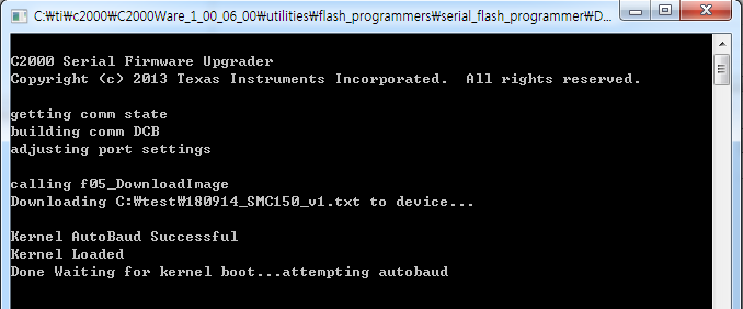
    2. If you run serial_flash_programmer
    It is suspended in the syntax of "Done Waiting for kernel ....".

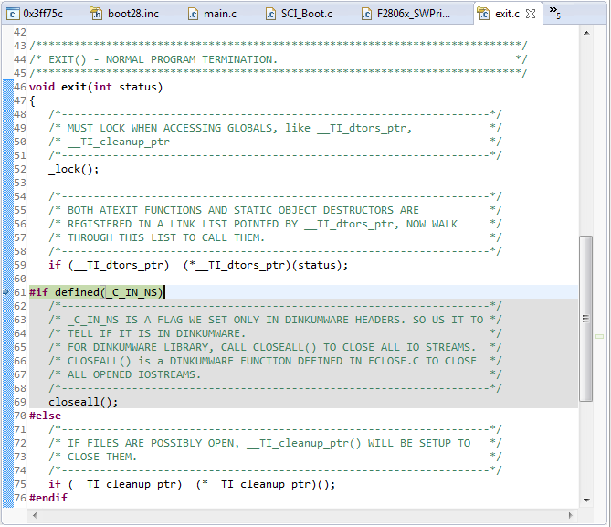
    3. At this time, dsp is already exited in debugging mode.

  • i guess the reliable method is to copy the code and include as part of your application as you were mentioning above.
  • What is the .asm or .c file that runs when the DSP is reset for the first time?
  • Where is init_Boot.asm called?
  • init_boot.asm contains a routine called _InitBoot. This routine is placed at the reset vector of the CPU. So when device resets this routine gets executed first.

    so you wont see any explicit SW call to _InitBoot anywhere in the code.
  • /*
    //###########################################################################
    //
    // FILE:    F28069.cmd
    //
    // TITLE:   Linker Command File For F28069 Device
    //
    //###########################################################################
    // $TI Release: F2806x C/C++ Header Files and Peripheral Examples V141 $ 
    // $Release Date: January 19, 2015 $ 
    // $Copyright: Copyright (C) 2011-2015 Texas Instruments Incorporated -
    //             http://www.ti.com/ ALL RIGHTS RESERVED $
    //###########################################################################
    */
    
    /* ======================================================
    // For Code Composer Studio V2.2 and later
    // ---------------------------------------
    // In addition to this memory linker command file,
    // add the header linker command file directly to the project.
    // The header linker command file is required to link the
    // peripheral structures to the proper locations within
    // the memory map.
    //
    // The header linker files are found in <base>\F2806x_headers\cmd
    //
    // For BIOS applications add:      F2806x_Headers_BIOS.cmd
    // For nonBIOS applications add:   F2806x_Headers_nonBIOS.cmd
    ========================================================= */
    
    /* ======================================================
    // For Code Composer Studio prior to V2.2
    // --------------------------------------
    // 1) Use one of the following -l statements to include the
    // header linker command file in the project. The header linker
    // file is required to link the peripheral structures to the proper
    // locations within the memory map                                    */
    
    /* Uncomment this line to include file only for non-BIOS applications */
    /* -l F2806x_Headers_nonBIOS.cmd */
    
    /* Uncomment this line to include file only for BIOS applications */
    /* -l F2806x_Headers_BIOS.cmd */
    
    /* 2) In your project add the path to <base>\F2806x_headers\cmd to the
       library search path under project->build options, linker tab,
       library search path (-i).
    /*========================================================= */
    
    /* Define the memory block start/length for the F2806x
       PAGE 0 will be used to organize program sections
       PAGE 1 will be used to organize data sections
    
       Notes:
             Memory blocks on F28069 are uniform (ie same
             physical memory) in both PAGE 0 and PAGE 1.
             That is the same memory region should not be
             defined for both PAGE 0 and PAGE 1.
             Doing so will result in corruption of program
             and/or data.
    
             Contiguous SARAM memory blocks can be combined
             if required to create a larger memory block.
    */
    
    MEMORY
    {
    PAGE 0 :   /* Program Memory */
               /* Memory (RAM/FLASH/OTP) blocks can be moved to PAGE1 for data allocation */
       RAML0       : origin = 0x008000, length = 0x000800     /* on-chip RAM block L0 */
       RAML1       : origin = 0x008800, length = 0x000400     /* on-chip RAM block L1 */
    OTP         : origin = 0x3D7800, length = 0x0003FB     /* on-chip OTP */
    
    KEY_BOOT    : origin = 0x3D7BFB, length = 0x000003	  /* Key Boot value in OTP */
    BOOT_MODE   : origin = 0x3D7BFE, length = 0x000003	  /* Boot mode selection */
    
       FLASHH      : origin = 0x3D8000, length = 0x004000     /* on-chip FLASH */
       FLASHG      : origin = 0x3DC000, length = 0x004000     /* on-chip FLASH */
       FLASHF      : origin = 0x3E0000, length = 0x004000     /* on-chip FLASH */
       FLASHE      : origin = 0x3E4000, length = 0x004000     /* on-chip FLASH */   
       FLASHD      : origin = 0x3E8000, length = 0x004000     /* on-chip FLASH */
       FLASHC      : origin = 0x3EC000, length = 0x004000     /* on-chip FLASH */
       FLASHA      : origin = 0x3F4000, length = 0x003F80     /* on-chip FLASH */
       CSM_RSVD    : origin = 0x3F7F80, length = 0x000076     /* Part of FLASHA.  Program with all 0x0000 when CSM is in use. */
       BEGIN       : origin = 0x3F7FF6, length = 0x000002     /* Part of FLASHA.  Used for "boot to Flash" bootloader mode. */
       CSM_PWL_P0  : origin = 0x3F7FF8, length = 0x000008     /* Part of FLASHA.  CSM password locations in FLASHA */
    
       FPUTABLES   : origin = 0x3FD860, length = 0x0006A0	  /* FPU Tables in Boot ROM */
       IQTABLES    : origin = 0x3FDF00, length = 0x000B50     /* IQ Math Tables in Boot ROM */
       IQTABLES2   : origin = 0x3FEA50, length = 0x00008C     /* IQ Math Tables in Boot ROM */
       IQTABLES3   : origin = 0x3FEADC, length = 0x0000AA	  /* IQ Math Tables in Boot ROM */
    
       ROM         : origin = 0x3FF3B0, length = 0x000C09     /* Boot ROM */
       FLASH_CHK   : origin = 0x3FFFB9, length = 0x000001
       VERSION     : origin = 0x3FFFBA, length = 0x000002
       CHECKSUM    : origin = 0x3FFFBC, length = 0x000004
       RESET       : origin = 0x3FFFC0, length = 0x000002     /* part of boot ROM  */
       VECTORS     : origin = 0x3FFFC2, length = 0x00003E     /* part of boot ROM  */
    
    PAGE 1 :   /* Data Memory */
               /* Memory (RAM/FLASH/OTP) blocks can be moved to PAGE0 for program allocation */
               /* Registers remain on PAGE1                                                  */
    
       BOOT_RSVD   : origin = 0x000000, length = 0x000050     /* Part of M0, BOOT rom will use this for stack */
       RAMM0       : origin = 0x000050, length = 0x0003B0     /* on-chip RAM block M0 */
       RAMM1       : origin = 0x000400, length = 0x000400     /* on-chip RAM block M1 */
       RAML2       : origin = 0x008C00, length = 0x000400     /* on-chip RAM block L2 */
       RAML3       : origin = 0x009000, length = 0x001000	  /* on-chip RAM block L3 */
       RAML4       : origin = 0x00A000, length = 0x002000     /* on-chip RAM block L4 */
       RAML5       : origin = 0x00C000, length = 0x002000     /* on-chip RAM block L5 */
       RAML6       : origin = 0x00E000, length = 0x002000     /* on-chip RAM block L6 */
       RAML7       : origin = 0x010000, length = 0x002000     /* on-chip RAM block L7 */
       RAML8       : origin = 0x012000, length = 0x002000     /* on-chip RAM block L8 */
       USB_RAM     : origin = 0x040000, length = 0x000800     /* USB RAM		  */   
       FLASHB      : origin = 0x3F0000, length = 0x004000     /* on-chip FLASH */     
    }
    
    /* Allocate sections to memory blocks.
       Note:
             codestart user defined section in DSP28_CodeStartBranch.asm used to redirect code
                       execution when booting to flash
             ramfuncs  user defined section to store functions that will be copied from Flash into RAM
    */
    
    
    SECTIONS
    {
    
       /* Allocate program areas: */
       .cinit              : > FLASHE,     PAGE = 0
       .pinit              : > FLASHE,     PAGE = 0
       .text               : > FLASHE,     PAGE = 0
       .InitBoot           : > FLASHE,     PAGE = 0
       codestart           : > BEGIN,      PAGE = 0
       ramfuncs            : LOAD = FLASHD,
                             RUN = RAML0,
                             LOAD_START(_RamfuncsLoadStart),
                             LOAD_END(_RamfuncsLoadEnd),
                             RUN_START(_RamfuncsRunStart),
    						 LOAD_SIZE(_RamfuncsLoadSize),
                             PAGE = 0
    
       csmpasswds          : > CSM_PWL_P0, PAGE = 0
       csm_rsvd            : > CSM_RSVD,   PAGE = 0
    
       /* Allocate uninitalized data sections: */
       .stack              : > RAMM0,           PAGE = 1
       .ebss               : > RAML2|RAML3,     PAGE = 1
       .esysmem            : > RAML2,           PAGE = 1
    
       /* Initalized sections to go in Flash */
       /* For SDFlash to program these, they must be allocated to page 0 */
       .econst             : > FLASHE,     PAGE = 0
       .switch             : > FLASHE,     PAGE = 0
       SciBootInit         : > FLASHA,     PAGE = 0
       BootMode			   : > BOOT_MODE,  PAGE = 0
       KeyBoot			   : > KEY_BOOT,   PAGE = 0
       .Flash          : load = FLASH_CHK  PAGE = 0
       .Checksum       : load = CHECKSUM,  PAGE = 0
       .Version        : load = VERSION,   PAGE = 0
    
       /* Allocate IQ math areas: */
       IQmath              : > FLASHE,     PAGE = 0            /* Math Code */
       IQmathTables        : > IQTABLES,   PAGE = 0, TYPE = NOLOAD
    
    
       /* Allocate FPU math areas: */
       FPUmathTables       : > FPUTABLES,  PAGE = 0, TYPE = NOLOAD
       
       DLOG				   : > RAML7,	   PAGE = 1
    
       DMARAML5	           : > RAML5,      PAGE = 1
       DMARAML6	           : > RAML6,      PAGE = 1
       DMARAML7	           : > RAML7,      PAGE = 1
       DMARAML8	           : > RAML8,      PAGE = 1   
    
    // FlashAPI        : LOAD = FLASH_API,  	PAGE = 0
    //	 {
    //	    -lFlash2806x_API_V100.lib(.text)
    //	    -lFlash2806x_API_V100.lib(.econst)
    //	 }
    //	 .romApiTable	 : LOAD = ROM_APITABLE, PAGE = 0
      /* Uncomment the section below if calling the IQNexp() or IQexp()
          functions from the IQMath.lib library in order to utilize the
          relevant IQ Math table in Boot ROM (This saves space and Boot ROM
          is 1 wait-state). If this section is not uncommented, IQmathTables2
          will be loaded into other memory (SARAM, Flash, etc.) and will take
          up space, but 0 wait-state is possible.
       */
       /*
       IQmathTables2    : > IQTABLES2, PAGE = 0, TYPE = NOLOAD
       {
    
                  IQmath.lib<IQNexpTable.obj> (IQmathTablesRam)
    
       }
       */
        /* Uncomment the section below if calling the IQNasin() or IQasin()
           functions from the IQMath.lib library in order to utilize the
           relevant IQ Math table in Boot ROM (This saves space and Boot ROM
           is 1 wait-state). If this section is not uncommented, IQmathTables2
           will be loaded into other memory (SARAM, Flash, etc.) and will take
           up space, but 0 wait-state is possible.
        */
        /*
        IQmathTables3    : > IQTABLES3, PAGE = 0, TYPE = NOLOAD
        {
    
                   IQmath.lib<IQNasinTable.obj> (IQmathTablesRam)
    
        }
        */
    
       /* .reset is a standard section used by the compiler.  It contains the */
       /* the address of the start of _c_int00 for C Code.   /*
       /* When using the boot ROM this section and the CPU vector */
       /* table is not needed.  Thus the default type is set here to  */
       /* DSECT  */
       .reset              : > RESET,      PAGE = 0, TYPE = DSECT
       vectors             : > VECTORS,    PAGE = 0, TYPE = DSECT
    
    }
    
    /*
    //===========================================================================
    // End of file.
    //===========================================================================
    */
    
    
        .global _ExitBoot
        .global _SciBootInit
        .ref _SelectBootMode
        .ref _c_int00
        .sect "SciBootInit" ;secure RAM location
    
    ;-----------------------------------------------
    ; _SciBoot
    ;-----------------------------------------------
    ;-----------------------------------------------
    ; This function performs the initial boot routine
    ; for the boot ROM.
    ;
    ; This module performs the following actions:
    ;
    ;     1) Initalizes the stack pointer
    ;     2) Sets the device for C28x operating mode
    ;     3) Calls the main boot functions
    ;     4) Calls an exit routine
    ;-----------------------------------------------
    
    
    _SciBootInit:
    
    ; Initalize the stack pointer.
    
    __stack:    .usect ".stack",0
        MOV SP, #__stack ; Initalize the stack pointer
    
    ; Initalize the device for running in C28x mode.
    
        C28OBJ       ; Select C28x object mode
        C28ADDR      ; Select C27x/C28x addressing
        C28MAP       ; Set blocks M0/M1 for C28x mode
        CLRC PAGE0   ; Always use stack addressing mode
        MOVW DP,#0   ; Initialize DP to point to the low 64 K
        CLRC OVM
    
    ; Set PM shift of 0
    
        SPM 0
    
    ; Decide which boot mode to use
        LCR  _SelectBootMode
    
    ; Cleanup and exit.  At this point the EntryAddr
    ; is located in the ACC register
        BF  _ExitBoot,UNC


    ;-----------------------------------------------
    ; _ExitBoot
    ;-----------------------------------------------
    ;-----------------------------------------------
    ;This module cleans up after the boot loader
    ;
    ; 1) Make sure the stack is deallocated.
    ;    SP = 0x400 after exiting the boot
    ;    loader
    ; 2) Push 0 onto the stack so RPC will be
    ;    0 after using LRETR to jump to the
    ;    entry point
    ; 2) Load RPC with the entry point
    ; 3) Clear all XARn registers
    ; 4) Clear ACC, P and XT registers
    ; 5) LRETR - this will also clear the RPC
    ;    register since 0 was on the stack
    ;-----------------------------------------------
    
    _ExitBoot:
    
    ;-----------------------------------------------
    ;   Insure that the stack is deallocated
    ;-----------------------------------------------
    
        MOV SP,#__stack
    
    ;-----------------------------------------------
    ; Clear the bottom of the stack.  This will endup
    ; in RPC when we are finished
    ;-----------------------------------------------
    
        MOV  *SP++,#0
        MOV  *SP++,#0
    
    ;-----------------------------------------------
    ; Load RPC with the entry point as determined
    ; by the boot mode.  This address will be returned
    ; in the ACC register.
    ;-----------------------------------------------
    
        PUSH ACC
        POP  RPC
    
    ;-----------------------------------------------
    ; Put registers back in their reset state.
    ;
    ; Clear all the XARn, ACC, XT, and P and DP
    ; registers
    ;
    ; NOTE: Leave the device in C28x operating mode
    ;       (OBJMODE = 1, AMODE = 0)
    ;-----------------------------------------------
        ZAPA
        MOVL  XT,ACC
        MOVZ  AR0,AL
        MOVZ  AR1,AL
        MOVZ  AR2,AL
        MOVZ  AR3,AL
        MOVZ  AR4,AL
        MOVZ  AR5,AL
        MOVZ  AR6,AL
        MOVZ  AR7,AL
        MOVW  DP, #0
    
    ;------------------------------------------------
    ;   Restore ST0 and ST1.  Note OBJMODE is
    ;   the only bit not restored to its reset state.
    ;   OBJMODE is left set for C28x object operating
    ;   mode.
    ;
    ;  ST0 = 0x0000     ST1 = 0x0A0B
    ;  15:10 OVC = 0    15:13      ARP = 0
    ;   9: 7  PM = 0       12       XF = 0
    ;      6   V = 0       11  M0M1MAP = 1
    ;      5   N = 0       10  reserved
    ;      4   Z = 0        9  OBJMODE = 1
    ;      3   C = 0        8    AMODE = 0
    ;      2  TC = 0        7 IDLESTAT = 0
    ;      1 OVM = 0        6   EALLOW = 0
    ;      0 SXM = 0        5     LOOP = 0
    ;                       4      SPA = 0
    ;                       3     VMAP = 1
    ;                       2    PAGE0 = 0
    ;                       1     DBGM = 1
    ;                       0     INTM = 1
    ;-----------------------------------------------
    
        MOV  *SP++,#0
        MOV  *SP++,#0x0A0B
        POP  ST1
        POP  ST0
    
    ;------------------------------------------------
    ;   Jump to the EntryAddr as defined by the
    ;   boot mode selected and continue execution
    ;-----------------------------------------------
    
        LRETR
    
    ;eof ----------
    
    	entry = (Uint32(*)())(0x3F4000);
    	entry();

    I have created and attached the files "SciBootInit.asm" and "F28069.cmd".
    I called "FLASHA" area in main.c and executed "serial_flash_programmer".
    The program stopped earlier than before.

    SciBootInit         : > FLASHA,     PAGE = 0

    The area of "SciBootInit" is assigned to the "FLASHA" area and my application is assigned to the "FLASHE" area.

  • you just need to copy the SCI_Boot() function and its dependencies to your application code and integrate.
    In above case you seem to take full boot code which is not needed.