This thread has been locked.

If you have a related question, please click the "Ask a related question" button in the top right corner. The newly created question will be automatically linked to this question.

CCS/TMS320F28032: A question about the compactor of 032

Part Number: TMS320F28032


Tool/software: Code Composer Studio

Hi, I'm Erwin, 

when we are using 28032(LQFP package), we found a strange waveform as below:

Configure COMP2A(14pin) and COMP3A(12pin) as the noninverting terminal of COMP2 and COMP3, internal DAC is connected to inverting terminal of COMP.

when ADC sample function of COMP2B(27pin) and COMP3B(29pin) were enabled, a strange waveform would happen in COMP2A(14pin) and COMP3A(12pin), as the picture shown, the frequency is same with the sample frequency.

if the ADC sample function of COMP2B(27pin) and COMP3B(29pin) were disabled, the phenomenon wouldn't happen.

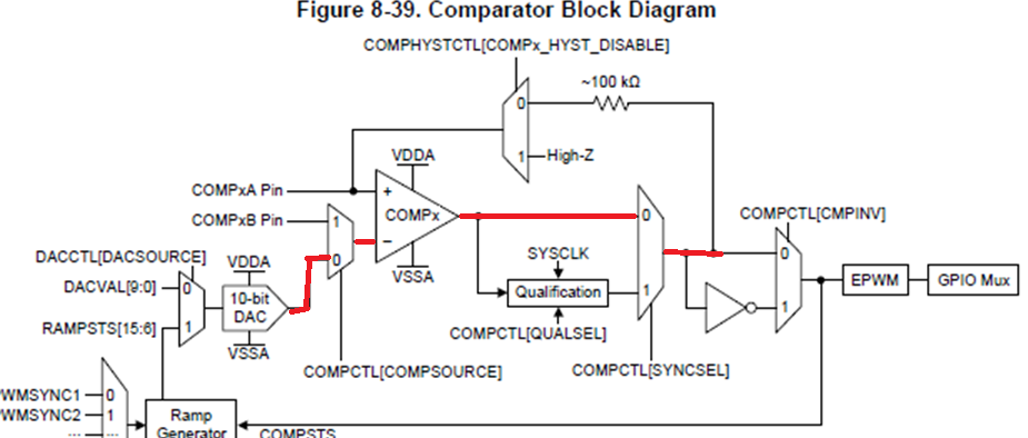
in my customer's application, P27 and P29 were connected to ground, COMPxB is not connected to the negative terminal directly, as the figure shown, the DAC was connected to the negative terminal of the comparator?

My question is, why this phenomenon would happen? do you have any suggestions to avoid it?

Thank you very much

related questions is here:

e2e.ti.com/.../745596

  • Erwin,

    Did you take my prior input into consideration? What happens if hysteresis is disabled?

    -Tommy
  • Erwin,

    It has been a while since your last update. I assume that you were able to resolve your issue.

    If not, please reply to this thread. If the thread has locked due to timeout, please create a new thread describing the current status of your issue.

    -Tommy
  • hi, Tommy,
    Sorry to reply you so late because my customer didn't give me answer.
    they set COMPX_HYST_DISABLE of COMPHYSCTL resistor to 1. this issue still alive.
    Do you need me to provide more information? please tell me.
    Thank you.

    erwin
  • Erwin,

    Do you have any more information about how their system is configured? Which ADC channels are used and how they are triggered? How the signals are conditioned or filtered on the board?

    Are ADC channels B4 and B6 used as well? There is a possibility for that to affect A4 and A6 if they have a large Rs value.

    -Tommy
  • Erwin,

    It has been a while since your last update. I assume that you were able to resolve your issue.

    If not, please reply to this thread. If the thread has locked due to timeout, please create a new thread describing the current status of your issue.

    -Tommy