Part Number: LAUNCHXL-F28069M
Other Parts Discussed in Thread: C2000WARE
Tool/software: Code Composer Studio
Hello,
This thread has been locked.
If you have a related question, please click the "Ask a related question" button in the top right corner. The newly created question will be automatically linked to this question.
Part Number: LAUNCHXL-F28069M
Other Parts Discussed in Thread: C2000WARE
Tool/software: Code Composer Studio
Hello,
Hi Nisha,
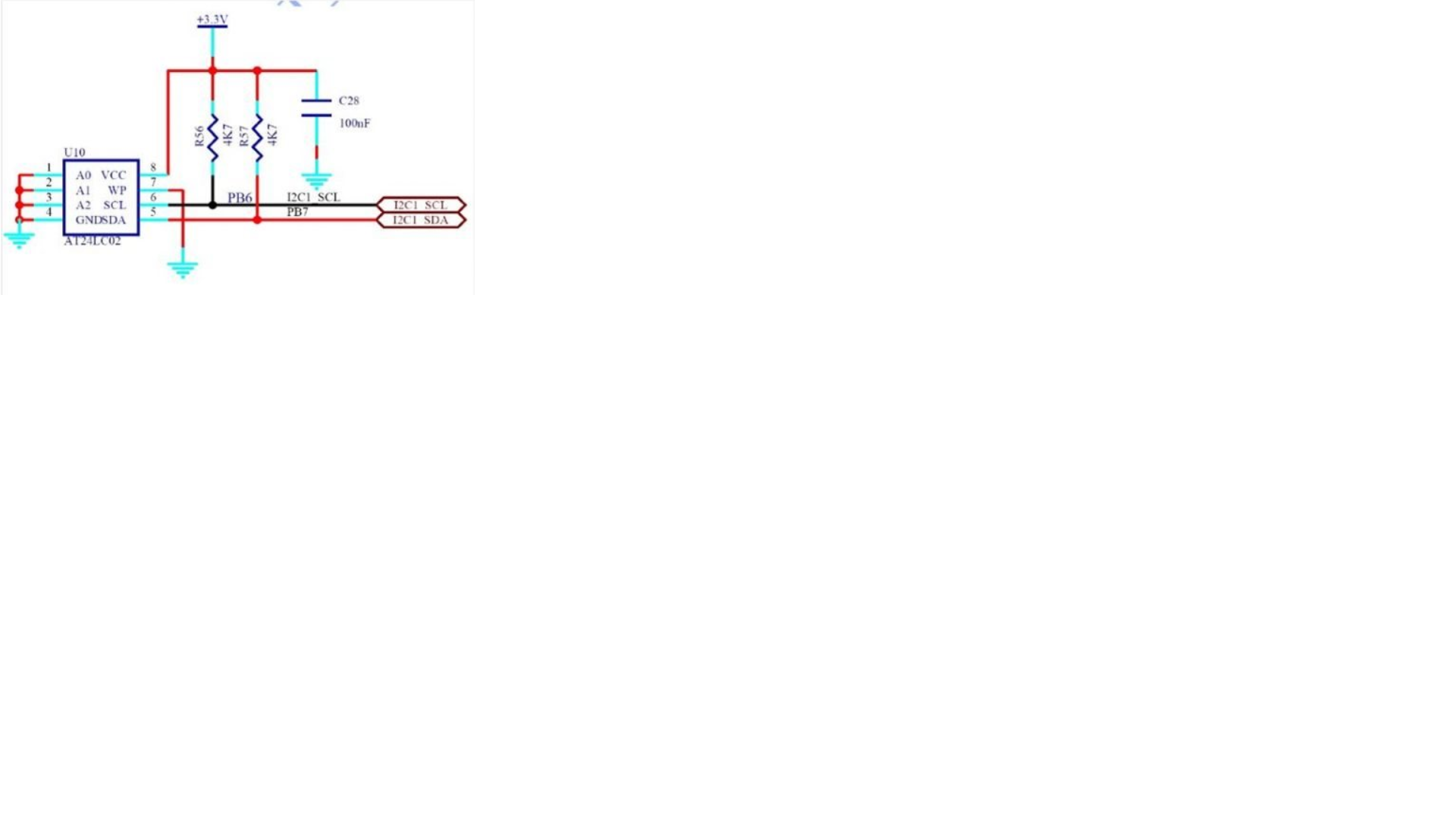
The on-board 93LC56BT-I/OT EEPROM is a SPI interface EEPROM only meant for the FTDI (XDS100 debugger) IC. It's not meant to be reprogrammed the way you are. Using an external EEPROM (like the AT24LC02) is the right thing to do as you've found.
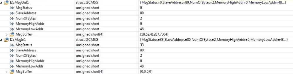
Stepping through the code may have inaccurate results since the I2C module is in FREE mode (continues to operate even at a breakpoint). You should run the code as normal and check the waveforms to better understand what's happening on the bus. Feel free to post waveforms here when interfacing with the AT24LC02. Also, in your image 3 the MsgStatus is "I2C_MSGSTAT_SEND_NOSTOP_BUSY" not "I2C_MSGSTAT_WRITE_BUSY".
Best,
Kevin
Kevin,
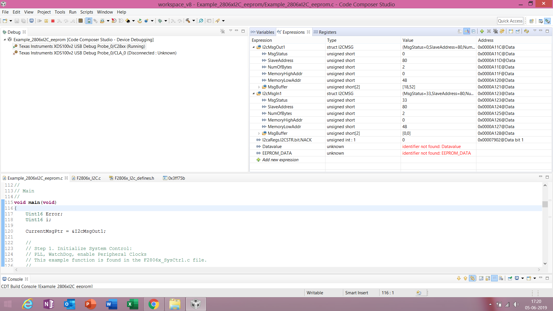
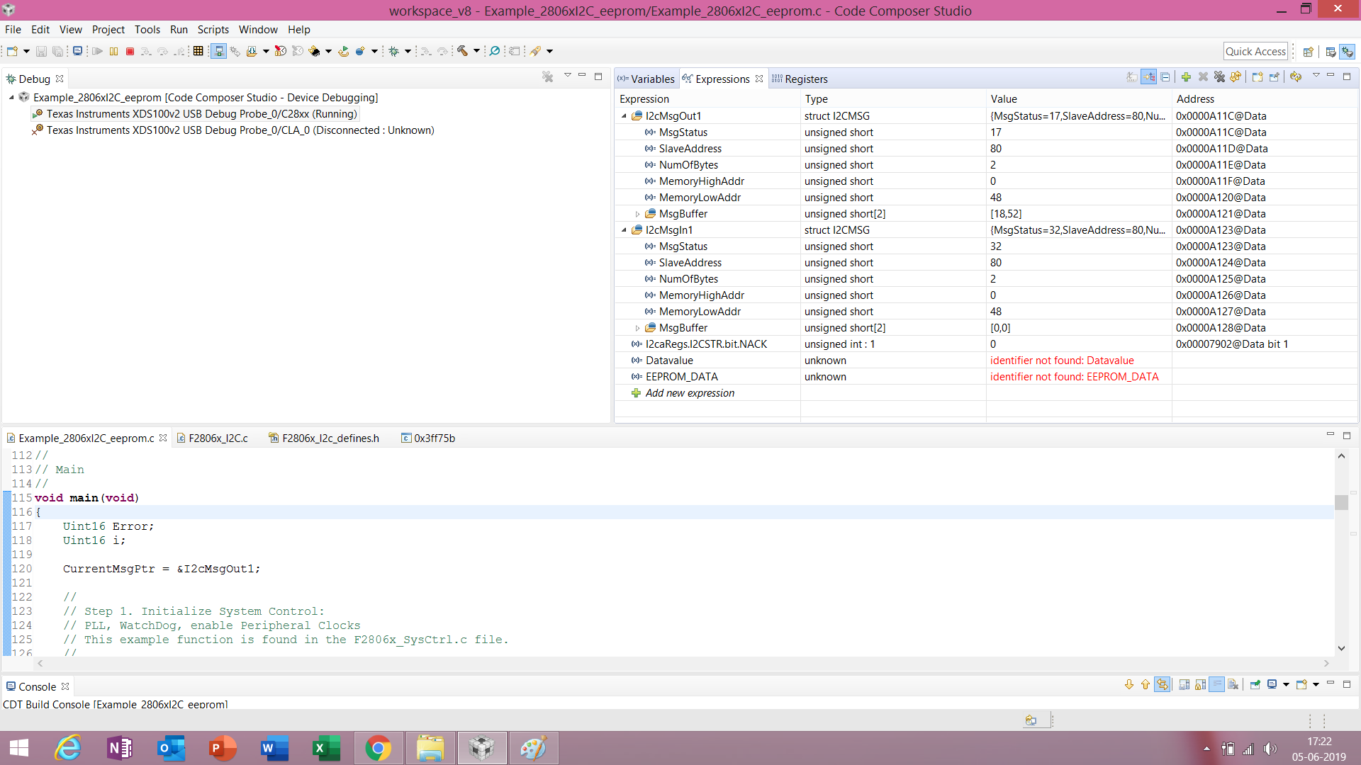
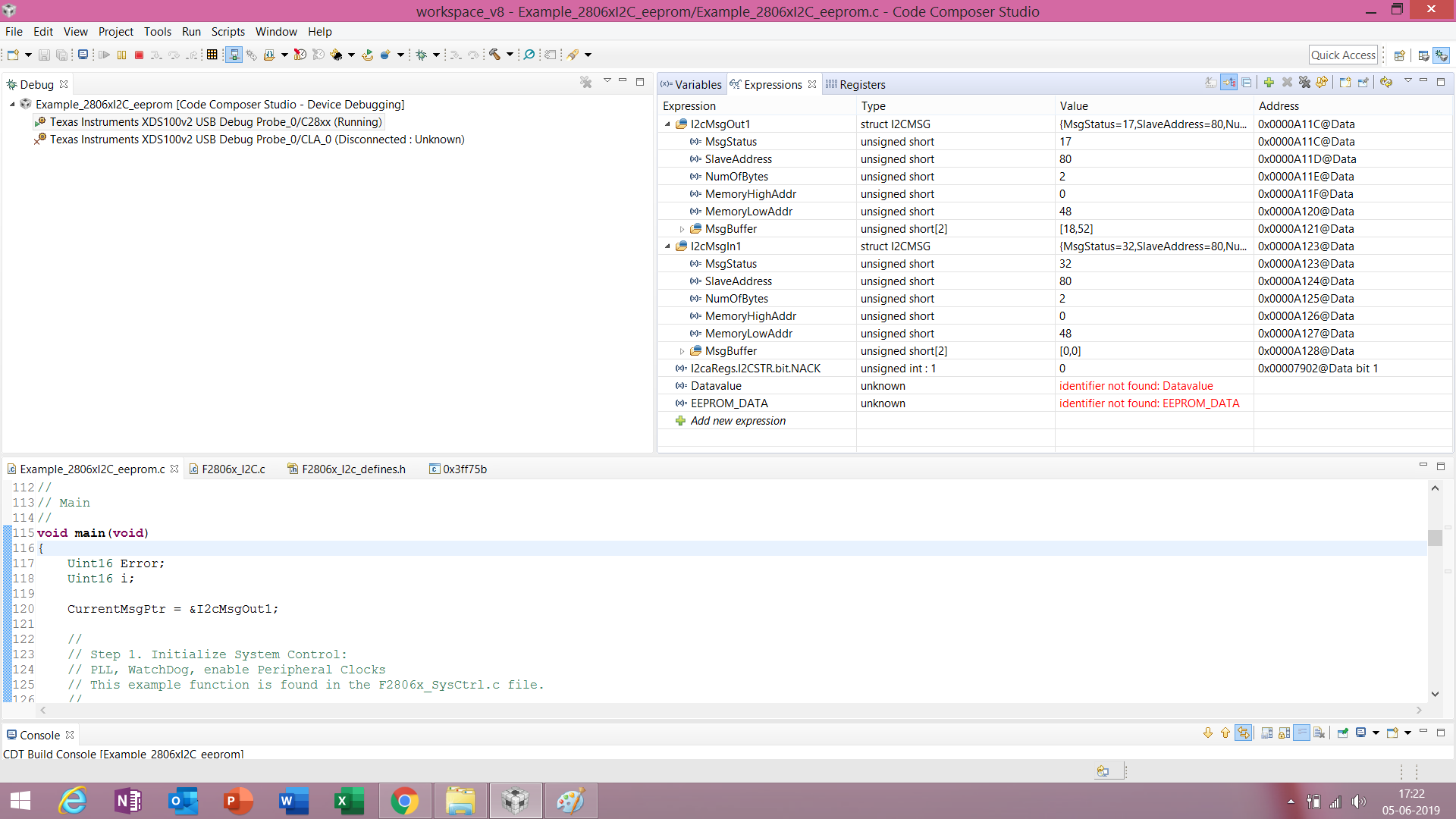
I have tried today by interfacing external eeprom 24C08WP (from STM) which is an 8 Kb eeprom. I have imported the code i2c eeprom and trying to run. Again I am unable to read the data. I am just using sample code, not made any changes. for I2cmsgOut1 I am receiving 0 status and some times I receive 17 status, but both the times I have not received the data..
I have attached the screenshots of both the conditions. I am getting NACK bit as 0. I have tried by using 3.3k resistors and 10nF cap. Also tried by using 4K7 resistor and 1nF cap for EEPROM hardware connections.I have attached my code here with. Please tell me, what is going wrong or send any working code.
//###########################################################################
//
// FILE: Example_2806xI2C_eeprom.c
//
// TITLE: I2C EEPROM Example
//
//! \addtogroup f2806x_example_list
//! <h1>I2C EEPROM(i2c_eeprom)</h1>
//!
//! This program requires an external I2C EEPROM connected to
//! the I2C bus at address 0x50.
//! This program will write 1-14 words to EEPROM and read them back.
//! The data written and the EEPROM address written to are contained
//! in the message structure, \b I2cMsgOut1. The data read back will be
//! contained in the message structure \b I2cMsgIn1.
//!
//! \note This program will only work on kits that have an on-board I2C EEPROM.
//!
//! \b Watch \b Variables \n
//! - I2cMsgIn1
//! - I2cMsgOut1
//
//###########################################################################
// $TI Release: F2806x Support Library v2.04.00.00 $
// $Release Date: Mon May 27 06:46:38 CDT 2019 $
// $Copyright:
// Copyright (C) 2009-2019 Texas Instruments Incorporated - http://www.ti.com/
//
// Redistribution and use in source and binary forms, with or without
// modification, are permitted provided that the following conditions
// are met:
//
// Redistributions of source code must retain the above copyright
// notice, this list of conditions and the following disclaimer.
//
// Redistributions in binary form must reproduce the above copyright
// notice, this list of conditions and the following disclaimer in the
// documentation and/or other materials provided with the
// distribution.
//
// Neither the name of Texas Instruments Incorporated nor the names of
// its contributors may be used to endorse or promote products derived
// from this software without specific prior written permission.
//
// THIS SOFTWARE IS PROVIDED BY THE COPYRIGHT HOLDERS AND CONTRIBUTORS
// "AS IS" AND ANY EXPRESS OR IMPLIED WARRANTIES, INCLUDING, BUT NOT
// LIMITED TO, THE IMPLIED WARRANTIES OF MERCHANTABILITY AND FITNESS FOR
// A PARTICULAR PURPOSE ARE DISCLAIMED. IN NO EVENT SHALL THE COPYRIGHT
// OWNER OR CONTRIBUTORS BE LIABLE FOR ANY DIRECT, INDIRECT, INCIDENTAL,
// SPECIAL, EXEMPLARY, OR CONSEQUENTIAL DAMAGES (INCLUDING, BUT NOT
// LIMITED TO, PROCUREMENT OF SUBSTITUTE GOODS OR SERVICES; LOSS OF USE,
// DATA, OR PROFITS; OR BUSINESS INTERRUPTION) HOWEVER CAUSED AND ON ANY
// THEORY OF LIABILITY, WHETHER IN CONTRACT, STRICT LIABILITY, OR TORT
// (INCLUDING NEGLIGENCE OR OTHERWISE) ARISING IN ANY WAY OUT OF THE USE
// OF THIS SOFTWARE, EVEN IF ADVISED OF THE POSSIBILITY OF SUCH DAMAGE.
// $
//###########################################################################
//
// Included Files
//
#include "DSP28x_Project.h" // Device Headerfile and Examples Include File
//
// Note: I2C Macros used in this example can be found in the
// F2806x_I2C_defines.h file
//
//
// Function Prototypes
//
void I2CA_Init(void);
Uint16 I2CA_WriteData(struct I2CMSG *msg);
Uint16 I2CA_ReadData(struct I2CMSG *msg);
__interrupt void i2c_int1a_isr(void);
void pass(void);
void fail(void);
//
// Defines
//
#define I2C_SLAVE_ADDR 0x50
#define I2C_NUMBYTES 2
#define I2C_EEPROM_HIGH_ADDR 0x00
#define I2C_EEPROM_LOW_ADDR 0x30
//
// Globals
//
// Two bytes will be used for the outgoing address,
// thus only setup 14 bytes maximum
//
struct I2CMSG I2cMsgOut1={I2C_MSGSTAT_SEND_WITHSTOP,
I2C_SLAVE_ADDR,
I2C_NUMBYTES,
I2C_EEPROM_HIGH_ADDR,
I2C_EEPROM_LOW_ADDR,
0x12, // Msg Byte 1
0x34
}; // Msg Byte 2
struct I2CMSG I2cMsgIn1={ I2C_MSGSTAT_SEND_NOSTOP,
I2C_SLAVE_ADDR,
I2C_NUMBYTES,
I2C_EEPROM_HIGH_ADDR,
I2C_EEPROM_LOW_ADDR};
struct I2CMSG *CurrentMsgPtr; // Used in interrupts
Uint16 PassCount;
Uint16 FailCount;
//
// Main
//
void main(void)
{
Uint16 Error;
Uint16 i;
CurrentMsgPtr = &I2cMsgOut1;
//
// Step 1. Initialize System Control:
// PLL, WatchDog, enable Peripheral Clocks
// This example function is found in the F2806x_SysCtrl.c file.
//
InitSysCtrl();
//
// Step 2. Initalize GPIO:
// This example function is found in the F2806x_Gpio.c file and
// illustrates how to set the GPIO to it's default state.
//
//InitGpio();
//
// Setup only the GP I/O only for I2C functionality
//
InitI2CGpio();
//
// Step 3. Clear all interrupts and initialize PIE vector table:
// Disable CPU interrupts
//
DINT;
//
// Initialize PIE control registers to their default state.
// The default state is all PIE interrupts disabled and flags
// are cleared.
// This function is found in the F2806x_PieCtrl.c file.
//
InitPieCtrl();
//
// Disable CPU interrupts and clear all CPU interrupt flags
//
IER = 0x0000;
IFR = 0x0000;
//
// Initialize the PIE vector table with pointers to the shell Interrupt
// Service Routines (ISR).
// This will populate the entire table, even if the interrupt
// is not used in this example. This is useful for debug purposes.
// The shell ISR routines are found in F2806x_DefaultIsr.c.
// This function is found in F2806x_PieVect.c.
//
InitPieVectTable();
//
// Interrupts that are used in this example are re-mapped to
// ISR functions found within this file.
//
EALLOW; // This is needed to write to EALLOW protected registers
PieVectTable.I2CINT1A = &i2c_int1a_isr;
EDIS; // This is needed to disable write to EALLOW protected registers
//
// Step 4. Initialize all the Device Peripherals:
// This function is found in F2806x_InitPeripherals.c
//
//InitPeripherals(); // Not required for this example
I2CA_Init();
//
// Step 5. User specific code
//
//
// Clear Counters
//
PassCount = 0;
FailCount = 0;
//
// Clear incoming message buffer
//
for (i = 0; i < I2C_MAX_BUFFER_SIZE; i++)
{
I2cMsgIn1.MsgBuffer[i] = 0x0000;
}
//
// Enable interrupts required for this example
//
//
// Enable I2C interrupt 1 in the PIE: Group 8 interrupt 1
//
PieCtrlRegs.PIEIER8.bit.INTx1 = 1;
//
// Enable CPU INT8 which is connected to PIE group 8
//
IER |= M_INT8;
EINT;
//
// Application loop
//
for(;;)
{
//
// Write data to EEPROM section
//
//
// Check the outgoing message to see if it should be sent.
// In this example it is initialized to send with a stop bit.
//
if(I2cMsgOut1.MsgStatus == I2C_MSGSTAT_SEND_WITHSTOP)
{
Error = I2CA_WriteData(&I2cMsgOut1);
//
// If communication is correctly initiated, set msg status to busy
// and update CurrentMsgPtr for the interrupt service routine.
// Otherwise, do nothing and try again next loop. Once message is
// initiated, the I2C interrupts will handle the rest. Search for
// i2c_int1a_isr in this file.
//
if (Error == I2C_SUCCESS)
{
CurrentMsgPtr = &I2cMsgOut1;
I2cMsgOut1.MsgStatus = I2C_MSGSTAT_WRITE_BUSY;
}
}
//
// Read data from EEPROM section
//
//
// Check outgoing message status. Bypass read section if status is
// not inactive.
//
if (I2cMsgOut1.MsgStatus == I2C_MSGSTAT_INACTIVE)
{
//
// Check incoming message status.
//
if(I2cMsgIn1.MsgStatus == I2C_MSGSTAT_SEND_NOSTOP)
{
//
// EEPROM address setup portion
//
while(I2CA_ReadData(&I2cMsgIn1) != I2C_SUCCESS)
{
//
// Maybe setup an attempt counter to break an infinite
// while loop. The EEPROM will send back a NACK while it is
// performing a write operation. Even though the write
// communique is complete at this point, the EEPROM could
// still be busy programming the data. Therefore, multiple
// attempts are necessary.
//
}
//
// Update current message pointer and message status
//
CurrentMsgPtr = &I2cMsgIn1;
I2cMsgIn1.MsgStatus = I2C_MSGSTAT_SEND_NOSTOP_BUSY;
}
//
// Once message has progressed past setting up the internal address
// of the EEPROM, send a restart to read the data bytes from the
// EEPROM. Complete the communique with a stop bit. MsgStatus is
// updated in the interrupt service routine.
//
else if(I2cMsgIn1.MsgStatus == I2C_MSGSTAT_RESTART)
{
//
// Read data portion
//
while(I2CA_ReadData(&I2cMsgIn1) != I2C_SUCCESS)
{
//
// Maybe setup an attempt counter to break an infinite
// while loop.
//
}
//
// Update current message pointer and message status
//
CurrentMsgPtr = &I2cMsgIn1;
I2cMsgIn1.MsgStatus = I2C_MSGSTAT_READ_BUSY;
}
}
}
}
//
// I2CA_Init -
//
void
I2CA_Init(void)
{
//
// Initialize I2C
//
I2caRegs.I2CSAR = I2C_SLAVE_ADDR; // Slave address - EEPROM control code
I2caRegs.I2CPSC.all = 6; // Prescaler - need 7-12 Mhz on module clk
I2caRegs.I2CCLKL = 10; // NOTE: must be non zero
I2caRegs.I2CCLKH = 5; // NOTE: must be non zero
I2caRegs.I2CIER.all = 0x24; // Enable SCD & ARDY interrupts
//
// Take I2C out of reset. Stop I2C when suspended
//
I2caRegs.I2CMDR.all = 0x0020;
I2caRegs.I2CFFTX.all = 0x6000; // Enable FIFO mode and TXFIFO
I2caRegs.I2CFFRX.all = 0x2040; // Enable RXFIFO, clear RXFFINT,
return;
}
//
// I2CA_WriteData -
//
Uint16
I2CA_WriteData(struct I2CMSG *msg)
{
Uint16 i;
//
// Wait until the STP bit is cleared from any previous master communication.
// Clearing of this bit by the module is delayed until after the SCD bit is
// set. If this bit is not checked prior to initiating a new message, the
// I2C could get confused.
//
if (I2caRegs.I2CMDR.bit.STP == 1)
{
return I2C_STP_NOT_READY_ERROR;
}
//
// Setup slave address
//
I2caRegs.I2CSAR = msg->SlaveAddress;
//
// Check if bus busy
//
if (I2caRegs.I2CSTR.bit.BB == 1)
{
return I2C_BUS_BUSY_ERROR;
}
//
// Setup number of bytes to send MsgBuffer + Address
//
I2caRegs.I2CCNT = msg->NumOfBytes+2;
//
// Setup data to send
//
I2caRegs.I2CDXR = msg->MemoryHighAddr;
I2caRegs.I2CDXR = msg->MemoryLowAddr;
// for (i=0; i<msg->NumOfBytes-2; i++)
for (i=0; i<msg->NumOfBytes; i++)
{
I2caRegs.I2CDXR = *(msg->MsgBuffer+i);
}
//
// Send start as master transmitter
//
I2caRegs.I2CMDR.all = 0x6E20;
return I2C_SUCCESS;
}
//
// I2CA_ReadData -
//
Uint16
I2CA_ReadData(struct I2CMSG *msg)
{
//
// Wait until the STP bit is cleared from any previous master communication.
// Clearing of this bit by the module is delayed until after the SCD bit is
// set. If this bit is not checked prior to initiating a new message, the
// I2C could get confused.
//
if (I2caRegs.I2CMDR.bit.STP == 1)
{
return I2C_STP_NOT_READY_ERROR;
}
I2caRegs.I2CSAR = msg->SlaveAddress;
if(msg->MsgStatus == I2C_MSGSTAT_SEND_NOSTOP)
{
//
// Check if bus busy
//
if (I2caRegs.I2CSTR.bit.BB == 1)
{
return I2C_BUS_BUSY_ERROR;
}
I2caRegs.I2CCNT = 2;
I2caRegs.I2CDXR = msg->MemoryHighAddr;
I2caRegs.I2CDXR = msg->MemoryLowAddr;
//
// Send data to setup EEPROM address
//
I2caRegs.I2CMDR.all = 0x2620;
}
else if(msg->MsgStatus == I2C_MSGSTAT_RESTART)
{
I2caRegs.I2CCNT = msg->NumOfBytes; // Setup how many bytes to expect
I2caRegs.I2CMDR.all = 0x2C20; // Send restart as master receiver
}
return I2C_SUCCESS;
}
//
// i2c_int1a_isr - I2C-A
//
__interrupt void
i2c_int1a_isr(void)
{
Uint16 IntSource, i;
//
// Read interrupt source
//
IntSource = I2caRegs.I2CISRC.all;
//
// Interrupt source = stop condition detected
//
if(IntSource == I2C_SCD_ISRC)
{
//
// If completed message was writing data, reset msg to inactive state
//
if (CurrentMsgPtr->MsgStatus == I2C_MSGSTAT_WRITE_BUSY)
{
CurrentMsgPtr->MsgStatus = I2C_MSGSTAT_INACTIVE;
}
else
{
//
// If a message receives a NACK during the address setup portion
// of the EEPROM read, the code further below included in the
// register access ready interrupt source code will generate a stop
// condition. After the stop condition is received (here), set the
// message status to try again. User may want to limit the number
// of retries before generating an error.
//
if(CurrentMsgPtr->MsgStatus == I2C_MSGSTAT_SEND_NOSTOP_BUSY)
{
CurrentMsgPtr->MsgStatus = I2C_MSGSTAT_SEND_NOSTOP;
}
//
// If completed message was reading EEPROM data, reset msg to
// inactive state and read data from FIFO.
//
else if (CurrentMsgPtr->MsgStatus == I2C_MSGSTAT_READ_BUSY)
{
CurrentMsgPtr->MsgStatus = I2C_MSGSTAT_INACTIVE;
for(i=0; i < I2C_NUMBYTES; i++)
{
CurrentMsgPtr->MsgBuffer[i] = I2caRegs.I2CDRR;
}
//
// Check received data
//
for(i=0; i < I2C_NUMBYTES; i++)
{
if(I2cMsgIn1.MsgBuffer[i] == I2cMsgOut1.MsgBuffer[i])
{
PassCount++;
}
else
{
FailCount++;
}
}
if(PassCount == I2C_NUMBYTES)
{
pass();
}
else
{
fail();
}
}
}
}
//
// Interrupt source = Register Access Ready
// This interrupt is used to determine when the EEPROM address setup
// portion of the read data communication is complete. Since no stop bit is
// commanded, this flag tells us when the message has been sent instead of
// the SCD flag. If a NACK is received, clear the NACK bit and command a
// stop. Otherwise, move on to the read data portion of the communication.
//
else if(IntSource == I2C_ARDY_ISRC)
{
if(I2caRegs.I2CSTR.bit.NACK == 1)
{
I2caRegs.I2CMDR.bit.STP = 1;
I2caRegs.I2CSTR.all = I2C_CLR_NACK_BIT;
}
else if(CurrentMsgPtr->MsgStatus == I2C_MSGSTAT_SEND_NOSTOP_BUSY)
{
CurrentMsgPtr->MsgStatus = I2C_MSGSTAT_RESTART;
}
}
else
{
//
// Generate some error due to invalid interrupt source
//
__asm(" ESTOP0");
}
//
// Enable future I2C (PIE Group 8) interrupts
//
PieCtrlRegs.PIEACK.all = PIEACK_GROUP8;
}
//
// pass -
//
void
pass()
{
__asm(" ESTOP0");
for(;;);
}
//
// fail -
//
void
fail(void)
{
__asm(" ESTOP0");
for(;;);
}
//
// End of File
//
Additionally I want to ask is there any issue withe the slave address, High address and low address. I to decide all these parameters. In the datasheet of EEPROM they have not given such things.
Thanks & Regards,
Nisha
Kevin,
I have tried today by interfacing external eeprom 24C08WP (from STM) which is an 8 Kb eeprom. I have imported the code i2c eeprom and trying to run. Again I am unable to read the data. I am just using sample code, not made any changes. for I2cmsgOut1 I am receiving 0 status and some times I receive 17 status, but both the times I have not received the data..
I have attached the screenshots of both the conditions. I am getting NACK bit as 0. I have tried by using 3.3k resistors and 10nF cap. Also tried by using 4K7 resistor and 1nF cap for EEPROM hardware connections.I have attached my code here with. Please tell me, what is going wrong or send any working code.
//###########################################################################
//
// FILE: Example_2806xI2C_eeprom.c
//
// TITLE: I2C EEPROM Example
//
//! \addtogroup f2806x_example_list
//! <h1>I2C EEPROM(i2c_eeprom)</h1>
//!
//! This program requires an external I2C EEPROM connected to
//! the I2C bus at address 0x50.
//! This program will write 1-14 words to EEPROM and read them back.
//! The data written and the EEPROM address written to are contained
//! in the message structure, \b I2cMsgOut1. The data read back will be
//! contained in the message structure \b I2cMsgIn1.
//!
//! \note This program will only work on kits that have an on-board I2C EEPROM.
//!
//! \b Watch \b Variables \n
//! - I2cMsgIn1
//! - I2cMsgOut1
//
//###########################################################################
// $TI Release: F2806x Support Library v2.04.00.00 $
// $Release Date: Mon May 27 06:46:38 CDT 2019 $
// $Copyright:
// Copyright (C) 2009-2019 Texas Instruments Incorporated - http://www.ti.com/
//
// Redistribution and use in source and binary forms, with or without
// modification, are permitted provided that the following conditions
// are met:
//
// Redistributions of source code must retain the above copyright
// notice, this list of conditions and the following disclaimer.
//
// Redistributions in binary form must reproduce the above copyright
// notice, this list of conditions and the following disclaimer in the
// documentation and/or other materials provided with the
// distribution.
//
// Neither the name of Texas Instruments Incorporated nor the names of
// its contributors may be used to endorse or promote products derived
// from this software without specific prior written permission.
//
// THIS SOFTWARE IS PROVIDED BY THE COPYRIGHT HOLDERS AND CONTRIBUTORS
// "AS IS" AND ANY EXPRESS OR IMPLIED WARRANTIES, INCLUDING, BUT NOT
// LIMITED TO, THE IMPLIED WARRANTIES OF MERCHANTABILITY AND FITNESS FOR
// A PARTICULAR PURPOSE ARE DISCLAIMED. IN NO EVENT SHALL THE COPYRIGHT
// OWNER OR CONTRIBUTORS BE LIABLE FOR ANY DIRECT, INDIRECT, INCIDENTAL,
// SPECIAL, EXEMPLARY, OR CONSEQUENTIAL DAMAGES (INCLUDING, BUT NOT
// LIMITED TO, PROCUREMENT OF SUBSTITUTE GOODS OR SERVICES; LOSS OF USE,
// DATA, OR PROFITS; OR BUSINESS INTERRUPTION) HOWEVER CAUSED AND ON ANY
// THEORY OF LIABILITY, WHETHER IN CONTRACT, STRICT LIABILITY, OR TORT
// (INCLUDING NEGLIGENCE OR OTHERWISE) ARISING IN ANY WAY OUT OF THE USE
// OF THIS SOFTWARE, EVEN IF ADVISED OF THE POSSIBILITY OF SUCH DAMAGE.
// $
//###########################################################################
//
// Included Files
//
#include "DSP28x_Project.h" // Device Headerfile and Examples Include File
//
// Note: I2C Macros used in this example can be found in the
// F2806x_I2C_defines.h file
//
//
// Function Prototypes
//
void I2CA_Init(void);
Uint16 I2CA_WriteData(struct I2CMSG *msg);
Uint16 I2CA_ReadData(struct I2CMSG *msg);
__interrupt void i2c_int1a_isr(void);
void pass(void);
void fail(void);
//
// Defines
//
#define I2C_SLAVE_ADDR 0x50
#define I2C_NUMBYTES 2
#define I2C_EEPROM_HIGH_ADDR 0x00
#define I2C_EEPROM_LOW_ADDR 0x30
//
// Globals
//
// Two bytes will be used for the outgoing address,
// thus only setup 14 bytes maximum
//
struct I2CMSG I2cMsgOut1={I2C_MSGSTAT_SEND_WITHSTOP,
I2C_SLAVE_ADDR,
I2C_NUMBYTES,
I2C_EEPROM_HIGH_ADDR,
I2C_EEPROM_LOW_ADDR,
0x12, // Msg Byte 1
0x34
}; // Msg Byte 2
struct I2CMSG I2cMsgIn1={ I2C_MSGSTAT_SEND_NOSTOP,
I2C_SLAVE_ADDR,
I2C_NUMBYTES,
I2C_EEPROM_HIGH_ADDR,
I2C_EEPROM_LOW_ADDR};
struct I2CMSG *CurrentMsgPtr; // Used in interrupts
Uint16 PassCount;
Uint16 FailCount;
//
// Main
//
void main(void)
{
Uint16 Error;
Uint16 i;
CurrentMsgPtr = &I2cMsgOut1;
//
// Step 1. Initialize System Control:
// PLL, WatchDog, enable Peripheral Clocks
// This example function is found in the F2806x_SysCtrl.c file.
//
InitSysCtrl();
//
// Step 2. Initalize GPIO:
// This example function is found in the F2806x_Gpio.c file and
// illustrates how to set the GPIO to it's default state.
//
//InitGpio();
//
// Setup only the GP I/O only for I2C functionality
//
InitI2CGpio();
//
// Step 3. Clear all interrupts and initialize PIE vector table:
// Disable CPU interrupts
//
DINT;
//
// Initialize PIE control registers to their default state.
// The default state is all PIE interrupts disabled and flags
// are cleared.
// This function is found in the F2806x_PieCtrl.c file.
//
InitPieCtrl();
//
// Disable CPU interrupts and clear all CPU interrupt flags
//
IER = 0x0000;
IFR = 0x0000;
//
// Initialize the PIE vector table with pointers to the shell Interrupt
// Service Routines (ISR).
// This will populate the entire table, even if the interrupt
// is not used in this example. This is useful for debug purposes.
// The shell ISR routines are found in F2806x_DefaultIsr.c.
// This function is found in F2806x_PieVect.c.
//
InitPieVectTable();
//
// Interrupts that are used in this example are re-mapped to
// ISR functions found within this file.
//
EALLOW; // This is needed to write to EALLOW protected registers
PieVectTable.I2CINT1A = &i2c_int1a_isr;
EDIS; // This is needed to disable write to EALLOW protected registers
//
// Step 4. Initialize all the Device Peripherals:
// This function is found in F2806x_InitPeripherals.c
//
//InitPeripherals(); // Not required for this example
I2CA_Init();
//
// Step 5. User specific code
//
//
// Clear Counters
//
PassCount = 0;
FailCount = 0;
//
// Clear incoming message buffer
//
for (i = 0; i < I2C_MAX_BUFFER_SIZE; i++)
{
I2cMsgIn1.MsgBuffer[i] = 0x0000;
}
//
// Enable interrupts required for this example
//
//
// Enable I2C interrupt 1 in the PIE: Group 8 interrupt 1
//
PieCtrlRegs.PIEIER8.bit.INTx1 = 1;
//
// Enable CPU INT8 which is connected to PIE group 8
//
IER |= M_INT8;
EINT;
//
// Application loop
//
for(;;)
{
//
// Write data to EEPROM section
//
//
// Check the outgoing message to see if it should be sent.
// In this example it is initialized to send with a stop bit.
//
if(I2cMsgOut1.MsgStatus == I2C_MSGSTAT_SEND_WITHSTOP)
{
Error = I2CA_WriteData(&I2cMsgOut1);
//
// If communication is correctly initiated, set msg status to busy
// and update CurrentMsgPtr for the interrupt service routine.
// Otherwise, do nothing and try again next loop. Once message is
// initiated, the I2C interrupts will handle the rest. Search for
// i2c_int1a_isr in this file.
//
if (Error == I2C_SUCCESS)
{
CurrentMsgPtr = &I2cMsgOut1;
I2cMsgOut1.MsgStatus = I2C_MSGSTAT_WRITE_BUSY;
}
}
//
// Read data from EEPROM section
//
//
// Check outgoing message status. Bypass read section if status is
// not inactive.
//
if (I2cMsgOut1.MsgStatus == I2C_MSGSTAT_INACTIVE)
{
//
// Check incoming message status.
//
if(I2cMsgIn1.MsgStatus == I2C_MSGSTAT_SEND_NOSTOP)
{
//
// EEPROM address setup portion
//
while(I2CA_ReadData(&I2cMsgIn1) != I2C_SUCCESS)
{
//
// Maybe setup an attempt counter to break an infinite
// while loop. The EEPROM will send back a NACK while it is
// performing a write operation. Even though the write
// communique is complete at this point, the EEPROM could
// still be busy programming the data. Therefore, multiple
// attempts are necessary.
//
}
//
// Update current message pointer and message status
//
CurrentMsgPtr = &I2cMsgIn1;
I2cMsgIn1.MsgStatus = I2C_MSGSTAT_SEND_NOSTOP_BUSY;
}
//
// Once message has progressed past setting up the internal address
// of the EEPROM, send a restart to read the data bytes from the
// EEPROM. Complete the communique with a stop bit. MsgStatus is
// updated in the interrupt service routine.
//
else if(I2cMsgIn1.MsgStatus == I2C_MSGSTAT_RESTART)
{
//
// Read data portion
//
while(I2CA_ReadData(&I2cMsgIn1) != I2C_SUCCESS)
{
//
// Maybe setup an attempt counter to break an infinite
// while loop.
//
}
//
// Update current message pointer and message status
//
CurrentMsgPtr = &I2cMsgIn1;
I2cMsgIn1.MsgStatus = I2C_MSGSTAT_READ_BUSY;
}
}
}
}
//
// I2CA_Init -
//
void
I2CA_Init(void)
{
//
// Initialize I2C
//
I2caRegs.I2CSAR = I2C_SLAVE_ADDR; // Slave address - EEPROM control code
I2caRegs.I2CPSC.all = 6; // Prescaler - need 7-12 Mhz on module clk
I2caRegs.I2CCLKL = 10; // NOTE: must be non zero
I2caRegs.I2CCLKH = 5; // NOTE: must be non zero
I2caRegs.I2CIER.all = 0x24; // Enable SCD & ARDY interrupts
//
// Take I2C out of reset. Stop I2C when suspended
//
I2caRegs.I2CMDR.all = 0x0020;
I2caRegs.I2CFFTX.all = 0x6000; // Enable FIFO mode and TXFIFO
I2caRegs.I2CFFRX.all = 0x2040; // Enable RXFIFO, clear RXFFINT,
return;
}
//
// I2CA_WriteData -
//
Uint16
I2CA_WriteData(struct I2CMSG *msg)
{
Uint16 i;
//
// Wait until the STP bit is cleared from any previous master communication.
// Clearing of this bit by the module is delayed until after the SCD bit is
// set. If this bit is not checked prior to initiating a new message, the
// I2C could get confused.
//
if (I2caRegs.I2CMDR.bit.STP == 1)
{
return I2C_STP_NOT_READY_ERROR;
}
//
// Setup slave address
//
I2caRegs.I2CSAR = msg->SlaveAddress;
//
// Check if bus busy
//
if (I2caRegs.I2CSTR.bit.BB == 1)
{
return I2C_BUS_BUSY_ERROR;
}
//
// Setup number of bytes to send MsgBuffer + Address
//
I2caRegs.I2CCNT = msg->NumOfBytes+2;
//
// Setup data to send
//
I2caRegs.I2CDXR = msg->MemoryHighAddr;
I2caRegs.I2CDXR = msg->MemoryLowAddr;
// for (i=0; i<msg->NumOfBytes-2; i++)
for (i=0; i<msg->NumOfBytes; i++)
{
I2caRegs.I2CDXR = *(msg->MsgBuffer+i);
}
//
// Send start as master transmitter
//
I2caRegs.I2CMDR.all = 0x6E20;
return I2C_SUCCESS;
}
//
// I2CA_ReadData -
//
Uint16
I2CA_ReadData(struct I2CMSG *msg)
{
//
// Wait until the STP bit is cleared from any previous master communication.
// Clearing of this bit by the module is delayed until after the SCD bit is
// set. If this bit is not checked prior to initiating a new message, the
// I2C could get confused.
//
if (I2caRegs.I2CMDR.bit.STP == 1)
{
return I2C_STP_NOT_READY_ERROR;
}
I2caRegs.I2CSAR = msg->SlaveAddress;
if(msg->MsgStatus == I2C_MSGSTAT_SEND_NOSTOP)
{
//
// Check if bus busy
//
if (I2caRegs.I2CSTR.bit.BB == 1)
{
return I2C_BUS_BUSY_ERROR;
}
I2caRegs.I2CCNT = 2;
I2caRegs.I2CDXR = msg->MemoryHighAddr;
I2caRegs.I2CDXR = msg->MemoryLowAddr;
//
// Send data to setup EEPROM address
//
I2caRegs.I2CMDR.all = 0x2620;
}
else if(msg->MsgStatus == I2C_MSGSTAT_RESTART)
{
I2caRegs.I2CCNT = msg->NumOfBytes; // Setup how many bytes to expect
I2caRegs.I2CMDR.all = 0x2C20; // Send restart as master receiver
}
return I2C_SUCCESS;
}
//
// i2c_int1a_isr - I2C-A
//
__interrupt void
i2c_int1a_isr(void)
{
Uint16 IntSource, i;
//
// Read interrupt source
//
IntSource = I2caRegs.I2CISRC.all;
//
// Interrupt source = stop condition detected
//
if(IntSource == I2C_SCD_ISRC)
{
//
// If completed message was writing data, reset msg to inactive state
//
if (CurrentMsgPtr->MsgStatus == I2C_MSGSTAT_WRITE_BUSY)
{
CurrentMsgPtr->MsgStatus = I2C_MSGSTAT_INACTIVE;
}
else
{
//
// If a message receives a NACK during the address setup portion
// of the EEPROM read, the code further below included in the
// register access ready interrupt source code will generate a stop
// condition. After the stop condition is received (here), set the
// message status to try again. User may want to limit the number
// of retries before generating an error.
//
if(CurrentMsgPtr->MsgStatus == I2C_MSGSTAT_SEND_NOSTOP_BUSY)
{
CurrentMsgPtr->MsgStatus = I2C_MSGSTAT_SEND_NOSTOP;
}
//
// If completed message was reading EEPROM data, reset msg to
// inactive state and read data from FIFO.
//
else if (CurrentMsgPtr->MsgStatus == I2C_MSGSTAT_READ_BUSY)
{
CurrentMsgPtr->MsgStatus = I2C_MSGSTAT_INACTIVE;
for(i=0; i < I2C_NUMBYTES; i++)
{
CurrentMsgPtr->MsgBuffer[i] = I2caRegs.I2CDRR;
}
//
// Check received data
//
for(i=0; i < I2C_NUMBYTES; i++)
{
if(I2cMsgIn1.MsgBuffer[i] == I2cMsgOut1.MsgBuffer[i])
{
PassCount++;
}
else
{
FailCount++;
}
}
if(PassCount == I2C_NUMBYTES)
{
pass();
}
else
{
fail();
}
}
}
}
//
// Interrupt source = Register Access Ready
// This interrupt is used to determine when the EEPROM address setup
// portion of the read data communication is complete. Since no stop bit is
// commanded, this flag tells us when the message has been sent instead of
// the SCD flag. If a NACK is received, clear the NACK bit and command a
// stop. Otherwise, move on to the read data portion of the communication.
//
else if(IntSource == I2C_ARDY_ISRC)
{
if(I2caRegs.I2CSTR.bit.NACK == 1)
{
I2caRegs.I2CMDR.bit.STP = 1;
I2caRegs.I2CSTR.all = I2C_CLR_NACK_BIT;
}
else if(CurrentMsgPtr->MsgStatus == I2C_MSGSTAT_SEND_NOSTOP_BUSY)
{
CurrentMsgPtr->MsgStatus = I2C_MSGSTAT_RESTART;
}
}
else
{
//
// Generate some error due to invalid interrupt source
//
__asm(" ESTOP0");
}
//
// Enable future I2C (PIE Group 8) interrupts
//
PieCtrlRegs.PIEACK.all = PIEACK_GROUP8;
}
//
// pass -
//
void
pass()
{
__asm(" ESTOP0");
for(;;);
}
//
// fail -
//
void
fail(void)
{
__asm(" ESTOP0");
for(;;);
}
//
// End of File
//
Additionally I want to ask is there any issue withe the slave address, High address and low address. I to decide all these parameters. In the datasheet of EEPROM they have not given such things.
Thanks & Regards,
Nisha
Nisha,
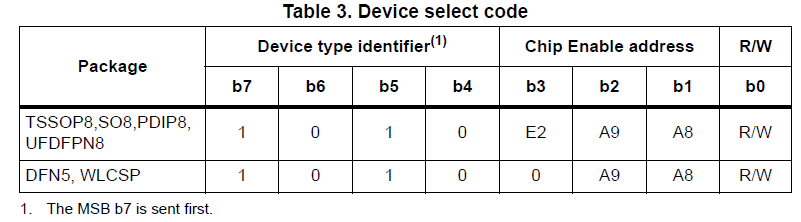
NISHA GOSAVI said:Additionally I want to ask is there any issue withe the slave address, High address and low address. I to decide all these parameters. In the datasheet of EEPROM they have not given such things.
The slave address for this device follows the bellow format from the 24C08WP datasheet. I'm not sure what A9/A8 bits are supposed to represent, you may need to ask the STM team.
The 24C08WP device uses only one Byte address, not both a High and Low byte. The data format should follow the below (once again from the 24C08WP device datasheet):
You'll need to edit the default i2c_eeprom code to match this data format.
Best,
Kevin
Kevin,
I have tried giving device address and memory addresses as per STM eeprom, but that is not working. I am receiving waveforms on I2C pins as I attached in above reply, but unable to read the data from eeprom. Today I have tried by using Atmel's eeprom 24c02 and run the sample code given in c2000ware, did not get any read. I have also tried by using the following codes, still not receiving any data. I have read so many threads, how is it possible that the people had run the same code for the same MCU and same eeprom which I am using and they got results, and I am not receiving any data. What is the actual reason. I am just trying to read and write a single byte, still not working. Till now I have tried three eeprom ICs. I kindly request you please tell me the reason or suggest the necessary changes in the code or send the whole working code instead of sending read write functions only.
Nisha
//////////////////////////
// Write data to EEPROM //
//////////////////////////
//I2C_SLAVE_ADDR = 0x50 address of the EEPROM
//I am writing 'h','e','l','l','o' to the EEPROM and then read it back later
//I2C_NUMBYTES = 5
//[MemoryHighAddr:MemoryLowAddr] -Address within the eeprom where you want to read/write
//Data[] has the word 'hello' and RxdData[] will store data read from the eeprom
I2caRegs.I2CSAR = I2C_SLAVE_ADDR; //Set slave address
I2caRegs.I2CCNT = I2C_NUMBYTES + 2; //Set count to 5 characters plus 2 address bytes
I2caRegs.I2CDXR = MemoryHighAddr; //Send eeprom high address
I2caRegs.I2CMDR.bit.TRX = 1; //Set to Transmit mode
I2caRegs.I2CMDR.bit.MST = 1; //Set to Master mode
I2caRegs.I2CMDR.bit.FREE = 1; //Run in FREE mode
I2caRegs.I2CMDR.bit.STP = 1; //Stop when internal counter becomes 0
I2caRegs.I2CMDR.bit.STT = 1; //Send the start bit, transmission will follow
while(I2caRegs.I2CSTR.bit.XRDY == 0){}; //Do nothing till data is shifted out
I2caRegs.I2CDXR = MemoryLowAddr; //Send eeprom low address
for(i = 0; i < I2C_NUMBYTES; i++){
while(I2caRegs.I2CSTR.bit.XRDY == 0){}; //Do nothing till data is shifted out
I2caRegs.I2CDXR = Data[i]; //Send out the message
}
//////////////////////////
// Read data from EEPROM//
//////////////////////////
I2caRegs.I2CSAR = I2C_SLAVE_ADDR; //Set slave address
I2caRegs.I2CCNT = 2; //Set count to 2 address bytes
I2caRegs.I2CDXR = MemoryHighAddr; //Send eeprom high address
I2caRegs.I2CMDR.bit.TRX = 1; //Set to Transmit mode
I2caRegs.I2CMDR.bit.MST = 1; //Set to Master mode
I2caRegs.I2CMDR.bit.FREE = 1; //Run in FREE mode
I2caRegs.I2CMDR.bit.STP = 0; //Dont release the bus after Tx
I2caRegs.I2CMDR.bit.STT = 1; //Send the start bit, transmission will follow
while(I2caRegs.I2CSTR.bit.XRDY == 0){}; //Do nothing till data is shifted out
I2caRegs.I2CDXR = MemoryLowAddr; //Send eeprom low address
I2caRegs.I2CCNT = I2C_NUMBYTES; //read 5 bytes from eeprom
I2caRegs.I2CMDR.bit.TRX = 0; //Set to Recieve mode
I2caRegs.I2CMDR.bit.MST = 1; //Set to Master mode
I2caRegs.I2CMDR.bit.FREE = 1; //Run in FREE mode
I2caRegs.I2CMDR.bit.STP = 1; //Stop when internal counter becomes 0
I2caRegs.I2CMDR.bit.STT = 1; //Repeated start, Reception will follow
for(i = 0; i < I2C_NUMBYTES; i++){
while(I2caRegs.I2CSTR.bit.RRDY == 0){}; //I2CDRR not ready to read?
RxdData[i] = I2caRegs.I2CDRR;
}
//#############################################################################
//
// File: f2802x_examples_ccsv4/i2c_eeprom/Example_F2802xI2c_eeprom.c
//
// Title: F2802x I2C EEPROM Example
//
// Group: C2000
// Target Device: TMS320F2802x
//
//! \addtogroup example_list
//! <h1>I2C EEPROM</h1>
//!
//! This program will write 1-14 words to EEPROM and read them back.
//! The data written and the EEPROM address written to are contained
//! in the message structure, I2cMsgOut1. The data read back will be
//! contained in the message structure I2cMsgIn1.
//!
//! This program will work with the on-board I2C EEPROM supplied on
//! the F2802x eZdsp or another EEPROM connected to the devices I2C bus
//! with a slave address of 0x50
//
// (C) Copyright 2012, Texas Instruments, Inc.
//#############################################################################
// $TI Release: f2802x Support Library v210 $
// $Release Date: Mon Sep 17 09:13:31 CDT 2012 $
//#############################################################################
#include "DSP28x_Project.h" // Device Headerfile and Examples Include File
// Note: I2C Macros used in this example can be found in the
// DSP2802x_I2C_defines.h file
// Prototype statements for functions found within this file.
void I2CA_Init(void);
Uint16 ReadEeprom(Uint16 e2promaddress);
void WriteEeprom(Uint16 e2promaddress, Uint16 data);
Uint32 DataRead[256];//] = { 0,0,0,0,0,0,0,0,0,0};
void main(void)
{
// Step 1. Initialize System Control:
// PLL, WatchDog, enable Peripheral Clocks
// This example function is found in the DSP2802x_SysCtrl.c file.
InitSysCtrl();
// Step 2. Initalize GPIO:
// This example function is found in the DSP2802x_Gpio.c file and
// illustrates how to set the GPIO to it's default state.
// InitGpio();
// Setup only the GP I/O only for I2C functionality
InitI2CGpio(); // using GPIO 32 and 33
// Step 3. Clear all interrupts and initialize PIE vector table:
// Disable CPU interrupts
DINT;
// Initialize PIE control registers to their default state.
// The default state is all PIE interrupts disabled and flags
// are cleared.
// This function is found in the DSP2802x_PieCtrl.c file.
InitPieCtrl();
// Disable CPU interrupts and clear all CPU interrupt flags:
IER = 0x0000;
IFR = 0x0000;
// If running from flash copy RAM only functions to RAM
#ifdef _FLASH
memcpy(&RamfuncsRunStart, &RamfuncsLoadStart, (size_t)&RamfuncsLoadSize);
#endif
// Initialize the PIE vector table with pointers to the shell Interrupt
// Service Routines (ISR).
// This will populate the entire table, even if the interrupt
// is not used in this example. This is useful for debug purposes.
// The shell ISR routines are found in DSP2802x_DefaultIsr.c.
// This function is found in DSP2802x_PieVect.c.
InitPieVectTable();
// Step 4. Initialize all the Device Peripherals:
// This function is found in DSP2802x_InitPeripherals.c
// InitPeripherals(); // Not required for this example
I2CA_Init();
DELAY_US(100);
// Step 5. User specific code
EINT;
unsigned int j;
j =0;
// Application loop
for(;;)
{
//WriteEeprom(j, 10+j);
//WriteEeprom(j+1, 10+j+1);
DataRead[j] = ReadEeprom(j);
//DataRead[j+1] = (ReadEeprom(j+1) << 8) | DataRead[j] ;
DataRead[j+1] = ReadEeprom(j+1) ;
j=j+2;
if (j>=200)
j = 0;
} // end of for(;;)
} // end of main
void I2CA_Init(void)
{
I2caRegs.I2CMDR.all = 0x0000;
// Initialize I2C
I2caRegs.I2CSAR = 0x0050; // Slave address - EEPROM control code
// I2CCLK = SYSCLK/(I2CPSC+1)
#if (CPU_FRQ_40MHZ||CPU_FRQ_50MHZ)
I2caRegs.I2CPSC.all = 4; // Prescaler - need 7-12 Mhz on module clk
#endif
#if (CPU_FRQ_60MHZ)
I2caRegs.I2CPSC.all = 5; //6 // Prescaler - need 7-12 Mhz on module clk
#endif
I2caRegs.I2CCLKL = 10; // NOTE: must be non zero
I2caRegs.I2CCLKH = 5; // NOTE: must be non zero
// I2caRegs.I2CIER.all = 0x24; // Enable SCD & ARDY interrupts
I2caRegs.I2CMDR.all = 0x0020; // Take I2C out of reset
// Stop I2C when suspended
I2caRegs.I2CFFTX.all = 0x6000; // Enable FIFO mode and TXFIFO
I2caRegs.I2CFFRX.all = 0x2040; // Enable RXFIFO, clear RXFFINT,
return;
}
Uint16 ReadEeprom(Uint16 e2promaddress)
{
Uint16 addresslow;
Uint16 addresshigh;
Uint16 tempdata;
I2caRegs.I2CMDR.bit.IRS = 1; // reset I2C
while (I2caRegs.I2CSTR.bit.BB == 1); // busy loop
I2caRegs.I2CSTR.bit.SCD = 1; // Clear the SCD bit (stop condition bit)
while(I2caRegs.I2CMDR.bit.STP == 1); // stop bit loop
addresshigh = e2promaddress>>8;
addresslow = e2promaddress;
I2caRegs.I2CSAR = 0x0050;
while (I2caRegs.I2CSTR.bit.BB == 1);
I2caRegs.I2CMDR.all = 0x2620; // start, no stop bit, master, tx, reset I2C
I2caRegs.I2CCNT = 0x0002;
I2caRegs.I2CDXR = addresshigh;
I2caRegs.I2CDXR = addresslow;
while(!I2caRegs.I2CSTR.bit.ARDY); // all ready?
I2caRegs.I2CMDR.all = 0x2C20; // start, stop bit when CNT =0, master, rx, reset I2C
I2caRegs.I2CCNT = 1;
if(I2caRegs.I2CSTR.bit.NACK == 1)
{
I2caRegs.I2CSTR.all = I2C_CLR_NACK_BIT; // 0x0002
}
I2caRegs.I2CMDR.bit.STP = 1; // stop bit when CNT=0
while(!I2caRegs.I2CSTR.bit.SCD); // stop bit detected?
//tempdata = I2caRegs.I2CDRR << 8; // read data
tempdata = I2caRegs.I2CDRR;
DELAY_US(100);
return(tempdata);
}
void WriteEeprom(Uint16 e2promaddress, Uint16 data)
{
Uint16 addresslow;
Uint16 addresshigh;
I2caRegs.I2CMDR.bit.IRS = 1; // reset I2C
addresshigh = (e2promaddress>>8)&0x00FF;
addresslow = e2promaddress&0x00FF;
I2caRegs.I2CSAR = 0x0050; // EEPROM control bits + address (A0-A2). for 24LC256, 0 1 0 1 0 A0 A1 A2
while (I2caRegs.I2CSTR.bit.BB == 1);
I2caRegs.I2CCNT = 3 ;
I2caRegs.I2CMDR.all = 0x6E20; //start, stop, no rm, reset i2c
I2caRegs.I2CDXR = addresshigh;
I2caRegs.I2CDXR = addresslow;
// I2caRegs.I2CDXR = (data >> 8) & 0x00FF; // high byte data
I2caRegs.I2CDXR = data; // low byte data
I2caRegs.I2CMDR.bit.STP = 1; // stop bit when CNT=0
while(!I2caRegs.I2CSTR.bit.SCD); // stop bit detected?
DELAY_US(5000); // 5ms = write cycle time of 24LC256 - based on datasheet 24LC256
return;
}
//===========================================================================
// No more.
//===========================================================================
// TI File $Revision: /main/3 $
// Checkin $Date: March 3, 2011 16:16:13 $
//###########################################################################
//
// FILE: Example_2806xI2c_eeprom.c
//
// TITLE: F2806x I2C EEPROM Example
//
// ASSUMPTIONS:
//
// This program requires the F2806x header files.
//
// This program requires an external I2C EEPROM connected to
// the I2C bus at address 0x50.
//
// As supplied, this project is configured for "boot to SARAM"
// operation. The F2806x Boot Mode table is shown below.
//
// $Boot_Table:
//
// While an emulator is connected to your device, the TRSTn pin = 1,
// which sets the device into EMU_BOOT boot mode. In this mode, the
// peripheral boot modes are as follows:
//
// Boot Mode: EMU_KEY EMU_BMODE
// (0xD00) (0xD01)
// ---------------------------------------
// Wait !=0x55AA X
// I/O 0x55AA 0x0000
// SCI 0x55AA 0x0001
// Wait 0x55AA 0x0002
// Get_Mode 0x55AA 0x0003
// SPI 0x55AA 0x0004
// I2C 0x55AA 0x0005
// OTP 0x55AA 0x0006
// ECANA 0x55AA 0x0007
// SARAM 0x55AA 0x000A <-- "Boot to SARAM"
// Flash 0x55AA 0x000B
// Wait 0x55AA Other
//
// Write EMU_KEY to 0xD00 and EMU_BMODE to 0xD01 via the debugger
// according to the Boot Mode Table above. Build/Load project,
// Reset the device, and Run example
//
// $End_Boot_Table
//
//
// Description:
//
// This program will write 1-14 words to EEPROM and read them back.
// The data written and the EEPROM address written to are contained
// in the message structure, I2cMsgOut1. The data read back will be
// contained in the message structure I2cMsgIn1.
//
//
//###########################################################################
// $TI Release: 2806x C/C++ Header Files V1.10 $
// $Release Date: April 7, 2011 $
//###########################################################################
#include "DSP28x_Project.h" // Device Headerfile and Examples Include File
// Note: I2C Macros used in this example can be found in the
// F2806x_I2C_defines.h file
// Prototype statements for functions found within this file.
void I2CA_Init(void);
Uint16 I2CA_WriteData(struct I2CMSG *msg);
Uint16 I2CA_ReadData(struct I2CMSG *msg);
interrupt void i2c_int1a_isr(void);
void Write_Data(Uint8 dido_id);
void Read_Data(Uint8 dido_id);
Uint16 I2CA_Random_ReadData(struct I2CMSG *msg);
Uint16 Error;
#define I2C_SLAVE_ADDR 0x50
#define I2C_NUMBYTES 2
#define I2C_R_NUMBYTES 2
#define I2C_EEPROM_HIGH_ADDR 0x00
#define I2C_EEPROM_LOW_ADDR0 0x00
#define I2C_EEPROM_LOW_ADDR1 0x01
#define I2C_EEPROM_LOW_ADDR2 0x02
#define I2C_EEPROM_LOW_ADDR3 0x03
#define I2C_EEPROM_LOW_ADDR4 0x04
// Global variables
// Two bytes will be used for the outgoing address,
// thus only setup 14 bytes maximum
/*
struct I2CMSG I2cMsgOut1={I2C_MSGSTAT_SEND_WITHSTOP,
I2C_SLAVE_ADDR,
I2C_NUMBYTES,
I2C_EEPROM_HIGH_ADDR,
I2C_EEPROM_LOW_ADDR1,
0x01, // Msg Byte 1
0x02
}; // Msg Byte 2
struct I2CMSG I2cMsgOut2={I2C_MSGSTAT_SEND_WITHSTOP,
I2C_SLAVE_ADDR,
I2C_NUMBYTES,
I2C_EEPROM_HIGH_ADDR,
I2C_EEPROM_LOW_ADDR2,
0x03, // Msg Byte 1
0x04}; // Msg Byte 2
struct I2CMSG I2cMsgOut3={I2C_MSGSTAT_SEND_WITHSTOP,
I2C_SLAVE_ADDR,
I2C_NUMBYTES,
I2C_EEPROM_HIGH_ADDR,
I2C_EEPROM_LOW_ADDR3,
0x05, // Msg Byte 1
0x06}; // Msg Byte 2
struct I2CMSG I2cMsgOut4={I2C_MSGSTAT_SEND_WITHSTOP,
I2C_SLAVE_ADDR,
I2C_NUMBYTES,
I2C_EEPROM_HIGH_ADDR,
I2C_EEPROM_LOW_ADDR4,
0x07, // Msg Byte 1
0x08}; // Msg Byte 2
struct I2CMSG I2cMsgIn1={ I2C_MSGSTAT_SEND_NOSTOP,
I2C_SLAVE_ADDR,
I2C_NUMBYTES,
I2C_EEPROM_HIGH_ADDR,
I2C_EEPROM_LOW_ADDR1
};
struct I2CMSG I2cMsgIn2={ I2C_MSGSTAT_SEND_NOSTOP,
I2C_SLAVE_ADDR,
I2C_NUMBYTES,
I2C_EEPROM_HIGH_ADDR,
I2C_EEPROM_LOW_ADDR2
};
struct I2CMSG I2cMsgIn3={ I2C_MSGSTAT_SEND_NOSTOP,
I2C_SLAVE_ADDR,
I2C_NUMBYTES,
I2C_EEPROM_HIGH_ADDR,
I2C_EEPROM_LOW_ADDR3
};
struct I2CMSG I2cMsgIn4={ I2C_MSGSTAT_SEND_NOSTOP,
I2C_SLAVE_ADDR,
I2C_NUMBYTES,
I2C_EEPROM_HIGH_ADDR,
I2C_EEPROM_LOW_ADDR4
};
*/
struct I2CMSG I2cMsgOut1[3]={
{
I2C_MSGSTAT_SEND_WITHSTOP,
I2C_SLAVE_ADDR,
I2C_NUMBYTES,
// I2C_EEPROM_HIGH_ADDR,
// I2C_EEPROM_LOW_ADDR0,
// 0x01, // Msg Byte 1
// 0x02
},
{
I2C_MSGSTAT_SEND_WITHSTOP,
I2C_SLAVE_ADDR,
I2C_NUMBYTES,
// I2C_EEPROM_HIGH_ADDR,
// I2C_EEPROM_LOW_ADDR1,
// 0x03, // Msg Byte 1
// 0x04
},
{
I2C_MSGSTAT_SEND_WITHSTOP,
I2C_SLAVE_ADDR,
I2C_NUMBYTES,
// I2C_EEPROM_HIGH_ADDR,
// I2C_EEPROM_LOW_ADDR1,
// 0x03, // Msg Byte 1
// 0x04
}
};// Msg Byte 1
struct I2CMSG I2cMsgIn1[3]={
{
I2C_MSGSTAT_SEND_NOSTOP,
I2C_SLAVE_ADDR,
I2C_R_NUMBYTES,
I2C_EEPROM_HIGH_ADDR,
I2C_EEPROM_LOW_ADDR0
},
{
I2C_MSGSTAT_SEND_NOSTOP,
I2C_SLAVE_ADDR,
I2C_R_NUMBYTES,
I2C_EEPROM_HIGH_ADDR,
I2C_EEPROM_LOW_ADDR1
},
{
I2C_MSGSTAT_SEND_NOSTOP,
I2C_SLAVE_ADDR,
I2C_R_NUMBYTES,
I2C_EEPROM_HIGH_ADDR,
I2C_EEPROM_LOW_ADDR2
}
};
struct I2CMSG *CurrentMsgPtr; // Used in interrupts
Uint16 PassCount;
Uint16 FailCount;
Uint16 Count;
void main(void)
{
// Uint16 Error;
Uint16 i;
// Step 1. Initialize System Control:
// PLL, WatchDog, enable Peripheral Clocks
// This example function is found in the F2806x_SysCtrl.c file.
InitSysCtrl();
// Step 2. Initalize GPIO:
// This example function is found in the F2806x_Gpio.c file and
// illustrates how to set the GPIO to it's default state.
// InitGpio();
// Setup only the GP I/O only for I2C functionality
InitI2CGpio();
// Step 3. Clear all interrupts and initialize PIE vector table:
// Disable CPU interrupts
DINT;
// Initialize PIE control registers to their default state.
// The default state is all PIE interrupts disabled and flags
// are cleared.
// This function is found in the F2806x_PieCtrl.c file.
InitPieCtrl();
// Disable CPU interrupts and clear all CPU interrupt flags:
IER = 0x0000;
IFR = 0x0000;
// Initialize the PIE vector table with pointers to the shell Interrupt
// Service Routines (ISR).
// This will populate the entire table, even if the interrupt
// is not used in this example. This is useful for debug purposes.
// The shell ISR routines are found in F2806x_DefaultIsr.c.
// This function is found in F2806x_PieVect.c.
InitPieVectTable();
// Interrupts that are used in this example are re-mapped to
// ISR functions found within this file.
EALLOW; // This is needed to write to EALLOW protected registers
PieVectTable.I2CINT1A = &i2c_int1a_isr;
EDIS; // This is needed to disable write to EALLOW protected registers
// Step 4. Initialize all the Device Peripherals:
// This function is found in F2806x_InitPeripherals.c
// InitPeripherals(); // Not required for this example
I2CA_Init();
// Step 5. User specific code
// Clear Counters
PassCount = 0;
FailCount = 0;
Count = 0;
// Clear incoming message buffer
for (i = 0; i < I2C_MAX_BUFFER_SIZE; i++)
{
I2cMsgIn1[0].MsgBuffer[i] = 0x0000;
I2cMsgIn1[1].MsgBuffer[i] = 0x0000;
I2cMsgIn1[2].MsgBuffer[i] = 0x0000;
// I2cMsgIn4.MsgBuffer[i] = 0x0000;
}
// Enable interrupts required for this example
// Enable I2C interrupt 1 in the PIE: Group 8 interrupt 1
PieCtrlRegs.PIEIER8.bit.INTx1 = 1;
// Enable CPU INT8 which is connected to PIE group 8
IER |= M_INT8;
EINT;
CurrentMsgPtr = &I2cMsgOut1[0];
I2cMsgOut1[0].MemoryHighAddr = 0x00;
I2cMsgOut1[0].MemoryLowAddr = 0x00;
I2cMsgOut1[0].MsgBuffer[0] = 0x11;
I2cMsgOut1[0].MsgBuffer[1] = 0x22;
I2cMsgOut1[1].MemoryHighAddr = 0x00;
I2cMsgOut1[1].MemoryLowAddr = 0x01;
I2cMsgOut1[1].MsgBuffer[0] = 0x07;
I2cMsgOut1[1].MsgBuffer[1] = 0x0E;
I2cMsgOut1[2].MemoryHighAddr = 0x00;
I2cMsgOut1[2].MemoryLowAddr = 0x02;
I2cMsgOut1[2].MsgBuffer[0] = 0x24;
I2cMsgOut1[2].MsgBuffer[1] = 0x36;
// Application loop
for(;;)
{
if(PassCount == 0)
{
CurrentMsgPtr = &I2cMsgOut1[0];
Write_Data(0);
}
if(PassCount == (1))
{
CurrentMsgPtr = &I2cMsgIn1[0];
Read_Data(0);
}
if(PassCount == 3)
{
CurrentMsgPtr = &I2cMsgOut1[0];
Write_Data(0);
}
if(PassCount == (2))
{
CurrentMsgPtr = &I2cMsgIn1[1];
Read_Data(1);
}
} // end of for(;;)
} // end of main
void I2CA_Init(void)
{
// Initialize I2C
I2caRegs.I2CSAR = 0x0050; // Slave address - EEPROM control code
I2caRegs.I2CPSC.all = 10; // Prescaler - need 7-12 Mhz on module clk
I2caRegs.I2CCLKL = 180; // NOTE: must be non zero
I2caRegs.I2CCLKH = 90; // NOTE: must be non zero
I2caRegs.I2CIER.all = 0x24; // Enable SCD & ARDY interrupts
I2caRegs.I2CMDR.all = 0x0020; // Take I2C out of reset
// Stop I2C when suspended
I2caRegs.I2CFFTX.all = 0x6000; // Enable FIFO mode and TXFIFO
I2caRegs.I2CFFRX.all = 0x2040; // Enable RXFIFO, clear RXFFINT,
return;
}
Uint16 I2CA_WriteData(struct I2CMSG *msg)
{
Uint16 i;
// Wait until the STP bit is cleared from any previous master communication.
// Clearing of this bit by the module is delayed until after the SCD bit is
// set. If this bit is not checked prior to initiating a new message, the
// I2C could get confused.
if (I2caRegs.I2CMDR.bit.STP == 1)
{
return I2C_STP_NOT_READY_ERROR;
}
// Setup slave address
I2caRegs.I2CSAR = msg->SlaveAddress;
// Check if bus busy
if (I2caRegs.I2CSTR.bit.BB == 1)
{
return I2C_BUS_BUSY_ERROR;
}
// Setup number of bytes to send
// MsgBuffer + Address
I2caRegs.I2CCNT = msg->NumOfBytes+2;
// Setup data to send
I2caRegs.I2CDXR = msg->MemoryHighAddr;
I2caRegs.I2CDXR = msg->MemoryLowAddr;
// for (i=0; i<msg->NumOfBytes-2; i++)
for (i=0; i<msg->NumOfBytes; i++)
{
I2caRegs.I2CDXR = *(msg->MsgBuffer+i);
}
// Send start as master transmitter
I2caRegs.I2CMDR.all = 0x6E20;
return I2C_SUCCESS;
}
Uint16 I2CA_ReadData(struct I2CMSG *msg)
{
// Wait until the STP bit is cleared from any previous master communication.
// Clearing of this bit by the module is delayed until after the SCD bit is
// set. If this bit is not checked prior to initiating a new message, the
// I2C could get confused.
if (I2caRegs.I2CMDR.bit.STP == 1)
{
return I2C_STP_NOT_READY_ERROR;
}
I2caRegs.I2CSAR = msg->SlaveAddress;
if(msg->MsgStatus == I2C_MSGSTAT_SEND_NOSTOP)
{
// Check if bus busy
if (I2caRegs.I2CSTR.bit.BB == 1)
{
return I2C_BUS_BUSY_ERROR;
}
I2caRegs.I2CCNT = 2;
I2caRegs.I2CDXR = msg->MemoryHighAddr;
I2caRegs.I2CDXR = msg->MemoryLowAddr;
I2caRegs.I2CMDR.all = 0x2620; // Send data to setup EEPROM address
}
else if(msg->MsgStatus == I2C_MSGSTAT_RESTART)
{
I2caRegs.I2CSAR = msg->SlaveAddress;
// Check if bus busy
/* if (I2caRegs.I2CSTR.bit.BB == 1)
{
return I2C_BUS_BUSY_ERROR;
}
*/
I2caRegs.I2CCNT = 2; // Setup how many bytes to expect
I2caRegs.I2CMDR.all = 0x2C20; // Send restart as master receiver
}
return I2C_SUCCESS;
}
interrupt void i2c_int1a_isr(void) // I2C-A
{
Uint16 IntSource, i;
// Read interrupt source
IntSource = I2caRegs.I2CISRC.all;
// Interrupt source = stop condition detected
if(IntSource == I2C_SCD_ISRC)
{
// If completed message was writing data, reset msg to inactive state
if (CurrentMsgPtr->MsgStatus == I2C_MSGSTAT_WRITE_BUSY)
{
CurrentMsgPtr->MsgStatus = I2C_MSGSTAT_INACTIVE;
FailCount++;
PassCount++;
}
else
{
// If a message receives a NACK during the address setup portion of the
// EEPROM read, the code further below included in the register access ready
// interrupt source code will generate a stop condition. After the stop
// condition is received (here), set the message status to try again.
// User may want to limit the number of retries before generating an error.
if(CurrentMsgPtr->MsgStatus == I2C_MSGSTAT_SEND_NOSTOP_BUSY)
{
CurrentMsgPtr->MsgStatus = I2C_MSGSTAT_SEND_NOSTOP;
}
// If completed message was reading EEPROM data, reset msg to inactive state
// and read data from FIFO.
else if (CurrentMsgPtr->MsgStatus == I2C_MSGSTAT_READ_BUSY)
{
CurrentMsgPtr->MsgStatus = I2C_MSGSTAT_INACTIVE;
for(i=0; i < 2; i++)
{
CurrentMsgPtr->MsgBuffer[i] = I2caRegs.I2CDRR;
}
PassCount++;
Count++;
}
}
} // end of stop condition detected
// Interrupt source = Register Access Ready
// This interrupt is used to determine when the EEPROM address setup portion of the
// read data communication is complete. Since no stop bit is commanded, this flag
// tells us when the message has been sent instead of the SCD flag. If a NACK is
// received, clear the NACK bit and command a stop. Otherwise, move on to the read
// data portion of the communication.
else if(IntSource == I2C_ARDY_ISRC)
{
if(I2caRegs.I2CSTR.bit.NACK == 1)
{
I2caRegs.I2CMDR.bit.STP = 1;
I2caRegs.I2CSTR.all = I2C_CLR_NACK_BIT;
}
else if(CurrentMsgPtr->MsgStatus == I2C_MSGSTAT_SEND_NOSTOP_BUSY)
{
CurrentMsgPtr->MsgStatus = I2C_MSGSTAT_RESTART;
}
} // end of register access ready
else
{
// Generate some error due to invalid interrupt source
asm(" ESTOP0");
}
// Enable future I2C (PIE Group 8) interrupts
PieCtrlRegs.PIEACK.all = PIEACK_GROUP8;
}
//===========================================================================
// No more.
//===========================================================================
void Write_Data(Uint8 dido_id)
{
// Check the outgoing message to see if it should be sent.
// In this example it is initialized to send with a stop bit.
if(I2cMsgOut1[dido_id].MsgStatus == I2C_MSGSTAT_SEND_WITHSTOP)
{
Error = I2CA_WriteData(&I2cMsgOut1[dido_id]);
// If communication is correctly initiated, set msg status to busy
// and update CurrentMsgPtr for the interrupt service routine.
// Otherwise, do nothing and try again next loop. Once message is
// initiated, the I2C interrupts will handle the rest. Search for
// i2c_int1a_isr in this file.
if (Error == I2C_SUCCESS)
{
CurrentMsgPtr = &I2cMsgOut1[dido_id];
I2cMsgOut1[dido_id].MsgStatus = I2C_MSGSTAT_WRITE_BUSY;
}
}
}// end of write section
void Read_Data(Uint8 dido_id)
{
if(I2cMsgIn1[dido_id].MsgStatus == I2C_MSGSTAT_SEND_NOSTOP)
{
// EEPROM address setup portion
while(I2CA_ReadData(&I2cMsgIn1[dido_id]) != I2C_SUCCESS)
// while(I2CA_Random_ReadData(&I2cMsgIn1[dido_id]) != I2C_SUCCESS)
{
// Maybe setup an attempt counter to break an infinite while
// loop. The EEPROM will send back a NACK while it is performing
// a write operation. Even though the write communique is
// complete at this point, the EEPROM could still be busy
// programming the data. Therefore, multiple attempts are
// necessary.
}
// Update current message pointer and message status
CurrentMsgPtr = &I2cMsgIn1[dido_id];
I2cMsgIn1[dido_id].MsgStatus = I2C_MSGSTAT_SEND_NOSTOP_BUSY;
}
// Once message has progressed past setting up the internal address
// of the EEPROM, send a restart to read the data bytes from the
// EEPROM. Complete the communique with a stop bit. MsgStatus is
// updated in the interrupt service routine.
else if(I2cMsgIn1[dido_id].MsgStatus == I2C_MSGSTAT_RESTART)
{
// Read data portion
while(I2CA_ReadData(&I2cMsgIn1[dido_id]) != I2C_SUCCESS)
// while(I2CA_Random_ReadData(&I2cMsgIn1[dido_id]) != I2C_SUCCESS)
{
// Maybe setup an attempt counter to break an infinite while
// loop.
}
// Update current message pointer and message status
CurrentMsgPtr = &I2cMsgIn1[dido_id];
I2cMsgIn1[dido_id].MsgStatus = I2C_MSGSTAT_READ_BUSY;
}
}// end of read section
//###########################################################################
//
//! \addtogroup f2806x_example_list
//! <h1>I2C EEPROM(i2c_eeprom)</h1>
//!
//! This program requires an external I2C EEPROM connected to
//! the I2C bus at address 0x50.
//! This program will write 1-14 words to EEPROM and read them back.
//! The data written and the EEPROM address written to are contained
//! in the message structure, \b I2cMsgOut1. The data read back will be
//! contained in the message structure \b I2cMsgIn1.
//!
//! \note This program will only work on kits that have an on-board I2C EEPROM.
//!
//! \b Watch \b Variables \n
//! - I2cMsgIn1
//! - I2cMsgOut1
//
//###########################################################################
// $TI Release: F2806x C/C++ Header Files and Peripheral Examples V151 $
// $Release Date: February 2, 2016 $
// $Copyright: Copyright (C) 2011-2016 Texas Instruments Incorporated -
// http://www.ti.com/ ALL RIGHTS RESERVED $
//###########################################################################
#include "DSP28x_Project.h" // Device Headerfile and Examples Include File
// Note: I2C Macros used in this example can be found in the
// F2806x_I2C_defines.h file
// Prototype statements for functions found within this file.
void I2CA_Init(void);
Uint16 I2CA_WriteData(struct I2CMSG *msg);
Uint16 I2CA_ReadData(struct I2CMSG *msg);
__interrupt void i2c_int1a_isr(void);
void pass(void);
void fail(void);
#define I2C_SLAVE_ADDR 0x50
#define I2C_NUMBYTES 2
#define I2C_EEPROM_HIGH_ADDR 0x00
#define I2C_EEPROM_LOW_ADDR 0x30
// Global variables
// Two bytes will be used for the outgoing address,
// thus only setup 14 bytes maximum
struct I2CMSG I2cMsgOut1={I2C_MSGSTAT_SEND_WITHSTOP,
I2C_SLAVE_ADDR,
I2C_NUMBYTES,
I2C_EEPROM_HIGH_ADDR,
I2C_EEPROM_LOW_ADDR,
0x12, // Msg Byte 1
0x34}; // Msg Byte 2
struct I2CMSG I2cMsgIn1={ I2C_MSGSTAT_SEND_NOSTOP,
I2C_SLAVE_ADDR,
I2C_NUMBYTES,
I2C_EEPROM_HIGH_ADDR,
I2C_EEPROM_LOW_ADDR};
struct I2CMSG *CurrentMsgPtr; // Used in interrupts
Uint16 PassCount;
Uint16 FailCount;
Uint16 Error;
void main(void)
{
Uint16 i;
CurrentMsgPtr = &I2cMsgOut1;
// Step 1. Initialize System Control:
// PLL, WatchDog, enable Peripheral Clocks
// This example function is found in the F2806x_SysCtrl.c file.
InitSysCtrl();
// Step 2. Initalize GPIO:
// This example function is found in the F2806x_Gpio.c file and
// illustrates how to set the GPIO to it's default state.
// InitGpio();
// Setup only the GP I/O only for I2C functionality
InitI2CGpio();
// Step 3. Clear all interrupts and initialize PIE vector table:
// Disable CPU interrupts
DINT;
// Initialize PIE control registers to their default state.
// The default state is all PIE interrupts disabled and flags
// are cleared.
// This function is found in the F2806x_PieCtrl.c file.
InitPieCtrl();
// Disable CPU interrupts and clear all CPU interrupt flags:
IER = 0x0000;
IFR = 0x0000;
// Initialize the PIE vector table with pointers to the shell Interrupt
// Service Routines (ISR).
// This will populate the entire table, even if the interrupt
// is not used in this example. This is useful for debug purposes.
// The shell ISR routines are found in F2806x_DefaultIsr.c.
// This function is found in F2806x_PieVect.c.
InitPieVectTable();
// Interrupts that are used in this example are re-mapped to
// ISR functions found within this file.
EALLOW; // This is needed to write to EALLOW protected registers
PieVectTable.I2CINT1A = &i2c_int1a_isr;
EDIS; // This is needed to disable write to EALLOW protected registers
// Step 4. Initialize all the Device Peripherals:
// This function is found in F2806x_InitPeripherals.c
// InitPeripherals(); // Not required for this example
I2CA_Init();
// Step 5. User specific code
// Clear Counters
PassCount = 0;
FailCount = 0;
// Clear incoming message buffer
for (i = 0; i < I2C_MAX_BUFFER_SIZE; i++)
{
I2cMsgIn1.MsgBuffer[i] = 0x0000;
}
// Enable interrupts required for this example
// Enable I2C interrupt 1 in the PIE: Group 8 interrupt 1
PieCtrlRegs.PIEIER8.bit.INTx1 = 1;
// Enable CPU INT8 which is connected to PIE group 8
IER |= M_INT8;
EINT;
// Application loop
for(;;)
{
//////////////////////////////////
// Write data to EEPROM section //
//////////////////////////////////
// Check the outgoing message to see if it should be sent.
// In this example it is initialized to send with a stop bit.
if(I2cMsgOut1.MsgStatus == I2C_MSGSTAT_SEND_WITHSTOP)
{
Error = I2CA_WriteData(&I2cMsgOut1);
// If communication is correctly initiated, set msg status to busy
// and update CurrentMsgPtr for the interrupt service routine.
// Otherwise, do nothing and try again next loop. Once message is
// initiated, the I2C interrupts will handle the rest. Search for
// i2c_int1a_isr in this file.
if (Error == I2C_SUCCESS)
{
CurrentMsgPtr = &I2cMsgOut1;
I2cMsgOut1.MsgStatus = I2C_MSGSTAT_WRITE_BUSY;
}
} // end of write section
///////////////////////////////////
// Read data from EEPROM section //
///////////////////////////////////
// Check outgoing message status. Bypass read section if status is
// not inactive.
if (I2cMsgOut1.MsgStatus == I2C_MSGSTAT_INACTIVE)
{
// Check incoming message status.
if(I2cMsgIn1.MsgStatus == I2C_MSGSTAT_SEND_NOSTOP)
{
// EEPROM address setup portion
while(I2CA_ReadData(&I2cMsgIn1) != I2C_SUCCESS)
{
// Maybe setup an attempt counter to break an infinite while
// loop. The EEPROM will send back a NACK while it is performing
// a write operation. Even though the write communique is
// complete at this point, the EEPROM could still be busy
// programming the data. Therefore, multiple attempts are
// necessary.
}
// Update current message pointer and message status
CurrentMsgPtr = &I2cMsgIn1;
I2cMsgIn1.MsgStatus = I2C_MSGSTAT_SEND_NOSTOP_BUSY;
}
// Once message has progressed past setting up the internal address
// of the EEPROM, send a restart to read the data bytes from the
// EEPROM. Complete the communique with a stop bit. MsgStatus is
// updated in the interrupt service routine.
else if(I2cMsgIn1.MsgStatus == I2C_MSGSTAT_RESTART)
{
// Read data portion
while(I2CA_ReadData(&I2cMsgIn1) != I2C_SUCCESS)
{
// Maybe setup an attempt counter to break an infinite while
// loop.
}
// Update current message pointer and message status
CurrentMsgPtr = &I2cMsgIn1;
I2cMsgIn1.MsgStatus = I2C_MSGSTAT_READ_BUSY;
}
} // end of read section
} // end of for(;;)
} // end of main
void I2CA_Init(void)
{
// Initialize I2C
I2caRegs.I2CSAR = 0x0050; // Slave address - EEPROM control code
I2caRegs.I2CPSC.all = 8; // Prescaler - need 7-12 Mhz on module clk
I2caRegs.I2CCLKL = 10; // NOTE: must be non zero
I2caRegs.I2CCLKH = 5; // NOTE: must be non zero
I2caRegs.I2CIER.all = 0x24; // Enable SCD & ARDY interrupts
I2caRegs.I2CMDR.all = 0x0020; // Take I2C out of reset
// Stop I2C when suspended
I2caRegs.I2CFFTX.all = 0x6000; // Enable FIFO mode and TXFIFO
I2caRegs.I2CFFRX.all = 0x2040; // Enable RXFIFO, clear RXFFINT,
return;
}
Uint16 I2CA_WriteData(struct I2CMSG *msg)
{
Uint16 i;
// Wait until the STP bit is cleared from any previous master communication.
// Clearing of this bit by the module is delayed until after the SCD bit is
// set. If this bit is not checked prior to initiating a new message, the
// I2C could get confused.
if (I2caRegs.I2CMDR.bit.STP == 1)
{
return I2C_STP_NOT_READY_ERROR;
}
// Setup slave address
I2caRegs.I2CSAR = msg->SlaveAddress;
// Check if bus busy
if (I2caRegs.I2CSTR.bit.BB == 1)
{
return I2C_BUS_BUSY_ERROR;
}
// Setup number of bytes to send
// MsgBuffer + Address
I2caRegs.I2CCNT = msg->NumOfBytes+2;
// Setup data to send
I2caRegs.I2CDXR = msg->MemoryHighAddr;
I2caRegs.I2CDXR = msg->MemoryLowAddr;
// for (i=0; i<msg->NumOfBytes-2; i++)
for (i=0; i<msg->NumOfBytes; i++)
{
I2caRegs.I2CDXR = *(msg->MsgBuffer+i);
}
// Send start as master transmitter
I2caRegs.I2CMDR.all = 0x6E20;
return I2C_SUCCESS;
}
Uint16 I2CA_ReadData(struct I2CMSG *msg)
{
// Wait until the STP bit is cleared from any previous master communication.
// Clearing of this bit by the module is delayed until after the SCD bit is
// set. If this bit is not checked prior to initiating a new message, the
// I2C could get confused.
if (I2caRegs.I2CMDR.bit.STP == 1)
{
return I2C_STP_NOT_READY_ERROR;
}
I2caRegs.I2CSAR = msg->SlaveAddress;
if(msg->MsgStatus == I2C_MSGSTAT_SEND_NOSTOP)
{
// Check if bus busy
if (I2caRegs.I2CSTR.bit.BB == 1)
{
return I2C_BUS_BUSY_ERROR;
}
I2caRegs.I2CCNT = 2;
I2caRegs.I2CDXR = msg->MemoryHighAddr;
I2caRegs.I2CDXR = msg->MemoryLowAddr;
I2caRegs.I2CMDR.all = 0x2620; // Send data to setup EEPROM address
}
else if(msg->MsgStatus == I2C_MSGSTAT_RESTART)
{
I2caRegs.I2CCNT = msg->NumOfBytes; // Setup how many bytes to expect
I2caRegs.I2CMDR.all = 0x2C20; // Send restart as master receiver
}
return I2C_SUCCESS;
}
__interrupt void i2c_int1a_isr(void) // I2C-A
{
Uint16 IntSource, i;
// Read interrupt source
IntSource = I2caRegs.I2CISRC.all;
// Interrupt source = stop condition detected
if(IntSource == I2C_SCD_ISRC)
{
// If completed message was writing data, reset msg to inactive state
if (CurrentMsgPtr->MsgStatus == I2C_MSGSTAT_WRITE_BUSY)
{
CurrentMsgPtr->MsgStatus = I2C_MSGSTAT_INACTIVE;
}
else
{
// If a message receives a NACK during the address setup portion of the
// EEPROM read, the code further below included in the register access ready
// interrupt source code will generate a stop condition. After the stop
// condition is received (here), set the message status to try again.
// User may want to limit the number of retries before generating an error.
if(CurrentMsgPtr->MsgStatus == I2C_MSGSTAT_SEND_NOSTOP_BUSY)
{
CurrentMsgPtr->MsgStatus = I2C_MSGSTAT_SEND_NOSTOP;
}
// If completed message was reading EEPROM data, reset msg to inactive state
// and read data from FIFO.
else if (CurrentMsgPtr->MsgStatus == I2C_MSGSTAT_READ_BUSY)
{
CurrentMsgPtr->MsgStatus = I2C_MSGSTAT_INACTIVE;
for(i=0; i < I2C_NUMBYTES; i++)
{
CurrentMsgPtr->MsgBuffer[i] = I2caRegs.I2CDRR;
}
{
// Check received data
for(i=0; i < I2C_NUMBYTES; i++)
{
if(I2cMsgIn1.MsgBuffer[i] == I2cMsgOut1.MsgBuffer[i])
{
PassCount++;
}
else
{
FailCount++;
}
}
if(PassCount == I2C_NUMBYTES)
{
pass();
}
else
{
fail();
}
}
}
}
} // end of stop condition detected
// Interrupt source = Register Access Ready
// This interrupt is used to determine when the EEPROM address setup portion of the
// read data communication is complete. Since no stop bit is commanded, this flag
// tells us when the message has been sent instead of the SCD flag. If a NACK is
// received, clear the NACK bit and command a stop. Otherwise, move on to the read
// data portion of the communication.
else if(IntSource == I2C_ARDY_ISRC)
{
if(I2caRegs.I2CSTR.bit.NACK == 1)
{
I2caRegs.I2CMDR.bit.STP = 1;
I2caRegs.I2CSTR.all = I2C_CLR_NACK_BIT;
}
else if(CurrentMsgPtr->MsgStatus == I2C_MSGSTAT_SEND_NOSTOP_BUSY)
{
CurrentMsgPtr->MsgStatus = I2C_MSGSTAT_RESTART;
}
} // end of register access ready
else
{
// Generate some error due to invalid interrupt source
__asm(" ESTOP0");
}
// Enable future I2C (PIE Group 8) interrupts
PieCtrlRegs.PIEACK.all = PIEACK_GROUP8;
}
void pass()
{
__asm(" ESTOP0");
for(;;);
}
void fail()
{
__asm(" ESTOP0");
for(;;);
}
//===========================================================================
// No more.
//===========================================================================
Nisha,
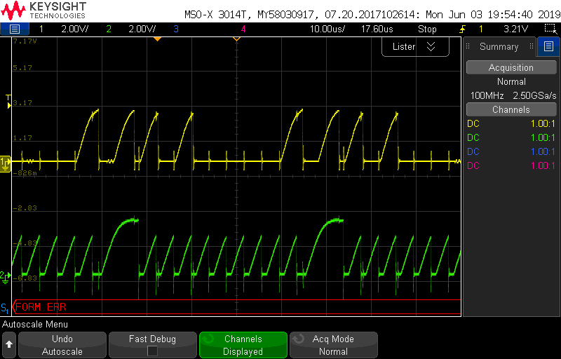
From your previous scope screen captures it looks like the rise times being experienced on the bus are quite long and may be out of the I2C spec. This might be due to the pull-up resistance or capacitance on the bus and they may need to be tweaked. I'd also suggest making sure the internal pull-ups of the C2000 device are disabled.
There's likely a good reason you aren't able to communicate with your epprom device successfully, which you'll need to investigate further by scoping the bus and checking the data that's being sent back and forth. Check that ACKs are being received/sent or investigate why a NACK is being recieved/sent. We don't typically review all of the user's code or provide full software applications specific to the user's usecase on this forum. You'll have to do this work on your own.
You may have better luck utilizing the functions I provided in this prior E2E post rather than the i2c_eeprom example on C2000ware:
https://e2e.ti.com/support/microcontrollers/c2000/f/171/t/773846
This SW is for F2802x, but the functions should be able to be used or easily ported to your F2806x device.
Best,
Kevin
Thanks Kevin for your kind attention.
I will check my pull ups and capacitance. Also execute the code given in the above thread. I will let you know the results soon.
Thanks & Regards,
Nisha
Nisha,
OK, that sounds good.
You will most likely need to edit the code from that thread to match your specific device. i.e. change slave address, control bytes, # of bytes written/read, etc. The code provided is designed for a different eeprom device.
Use the functions and follow the protocol / format provided in the Atmel 24c02 eeprom datasheet.
Best,
Kevin