This thread has been locked.

If you have a related question, please click the "Ask a related question" button in the top right corner. The newly created question will be automatically linked to this question.

[FAQ] Compiler/LAUNCHXL-F28379D: Updating default SCI echoback example developed for control card to work with Launchpad

Part Number: LAUNCHXL-F28379D
Other Parts Discussed in Thread: C2000WARE

Tool/software: TI C/C++ Compiler

Hello All,

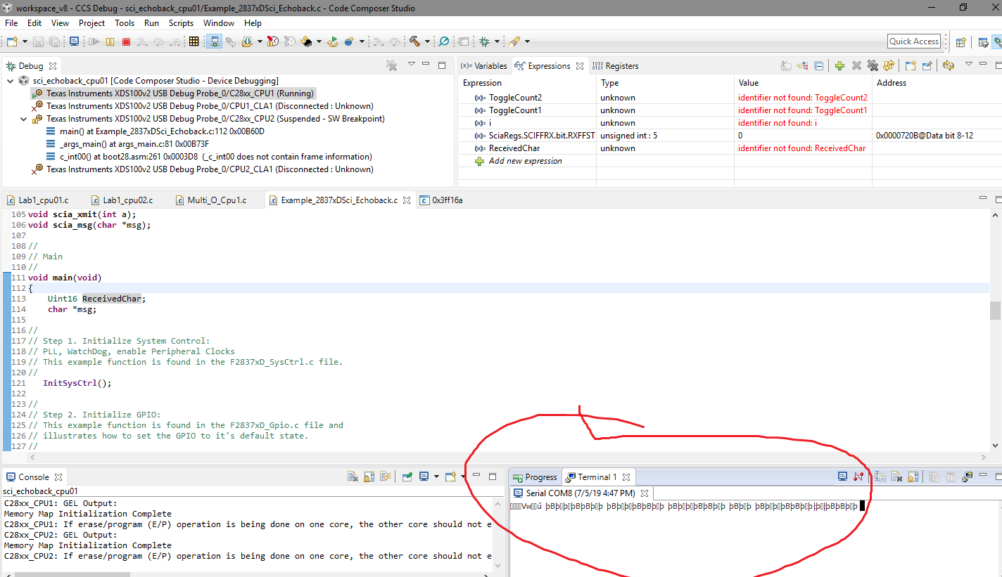
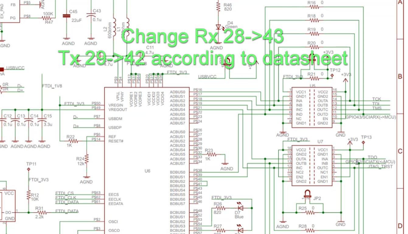
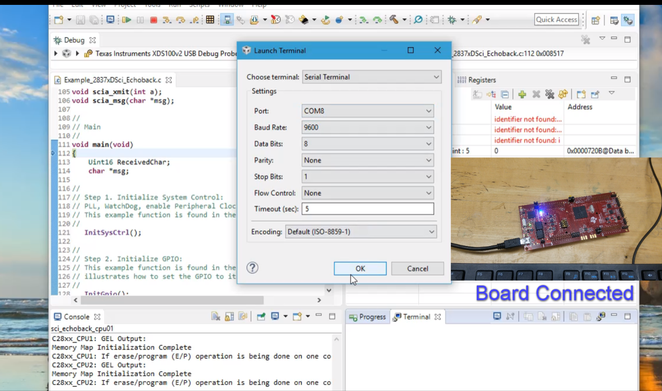
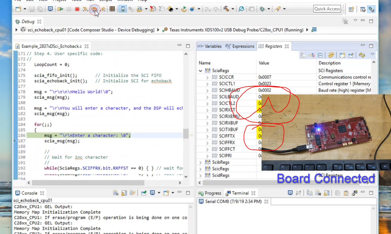
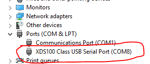
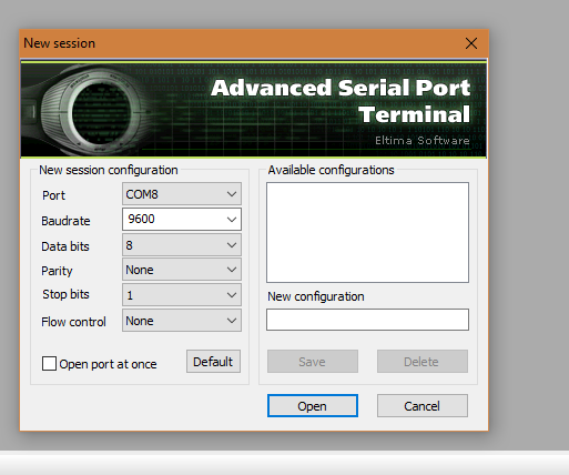
I am trying the Sci echo-back example on the LAUNCHXL-F28379D. I built the program and started the debug session. I opened the serial port according to the description

-

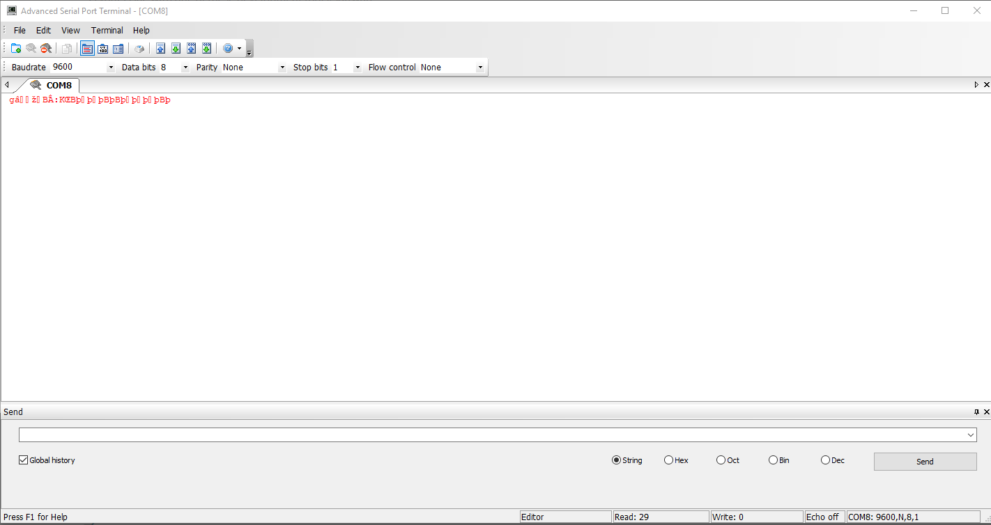
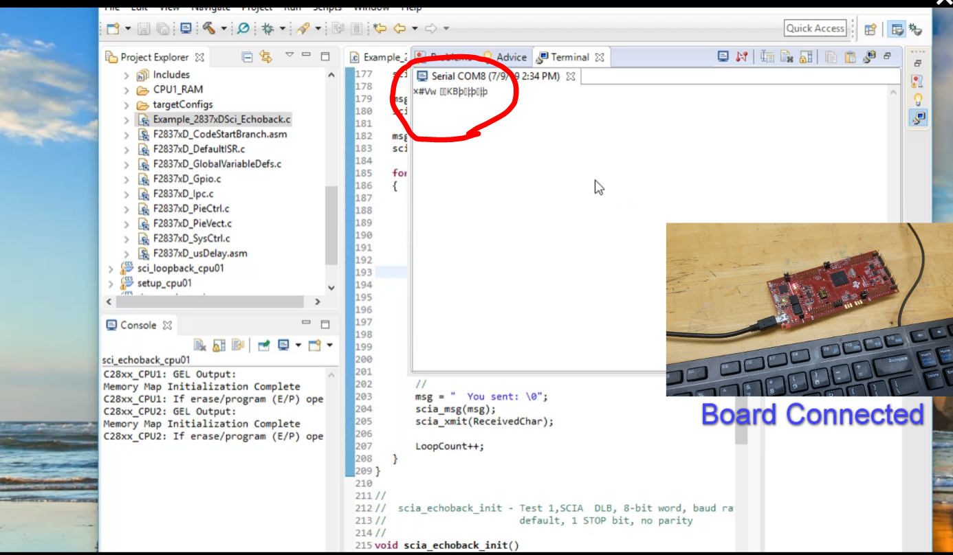
But I am getting this junk values.

I would really appreciate help solving this issue.

Thank you.

  • Hi Arindam ,

    It seems that the baud rate is not getting set correctly causing incorrect data to appear on the terminal.

    The examples in the C2000ware are mostly developed for the controlcard unless specified in the example or the project properties.

    If we want to use it with the Launchpad we would need to make some updates to the project configurations .

    Please check the section on "Getting Started and Troubleshooting " of the  C2000Ware_2_00_00_02\device_support\f2837xd\docs\F2837xD_DEV_USER_GUIDE.pdf

    If using a Launchpad, add a pre-define NAME called "_LAUNCHXL_F28379D". This is required to setup the proper device clocking.

    Regards.

  • Hello Meghana,

    Thank you for your response. As you suggested I have noticed that the Pre-define name was not declared. I changed it and rebuilt the program and started a debug session. The weird thing is during the debug session if I run the program I could not see anything on the terminal window ( though it was same earlier too). If I reset the board I started observing the same junk values still on the terminal happening at a certain frequency ~1 Hz. So it didn't solve the issue.

    I am a little bit confused as the same serial port is used to debug and as terminal too. Now is this supposed to create any issue?  Moreover, once I run the code am I supposed to see a working serial com between the board and terminal?

    Thank you. I really appreciate your help.

  • hi Arindam ,

    Have you looked at the GPIOs used for the terminal connections ? I guess the GPIO 42/ 43 are used in launchpad but the basic example uses some other pins.

    They might need an update to satisfy those needed by the launchpad.

    Regards.

  • Hello Meghana,

    Again thank you so much for your response. Now, let me describe my intended hardware functionality. I might be very wrong in the approach. 

    For this program, I am trying to write something in a serial terminal software ( To be transferred to the launchpad) (i.e. 'X') and expecting the same 'X' to be seen in the serial monitor (As an echo from the board) (Link between board and computer through same serial port /debug serial interface). Like an Arduino Serial feedback. 

    I might be very wrong as the Sci loopback might be written to transmit the data to one of its other serial port pins(not the one communicating to the computer/debug serial interface). In which case these serial port pin needs to be connected to the pc using another USB-Serial device. 

    Could you please clarify my understanding? Can I do the intended function  (Serial print as Arduino) with these board or I need external hardware connected to a USB serial converter which will be connected to a PC?

    I have changed the GPIO pins as per your advice but it's still the same.

    Thank you so much for answering.

  • hi ,

    Yes what you described is what happens in the  Sci echo-back example.

    The SCI loopback example sends to the TX and then there is an internal loopback ( without coming to the gpios / no PC connections ) , then put into the RX .

    No external hardware is needed.

    Can you reiterate what all you modified and where ? Paste the code if needed...

    I grabbed a F28377S launchpad to try the example and all i did is add the predefine and change the gpio pin muxing to map to the right sci pins.

    Regards.

  • Hello Meghana,


    Listed is the step by step description that I followed-


    1. I uninstalled the c2000 ware just to have it reinstalled and a fresh copy of the example.
    2. I installed c2000 and imported the Sci_loopback_cpu1 example

    3. I added _LAUNCHXL_F28379D as predefined symbols.

    4. I changed the pins Rx->43 and Tx->42. Can be seen in the figure.

    5. I built the program and started debugging.
    6. I have opened a terminal on CCS terminal window.

    7. During debug the sci register change was observed but no output on the terminal while hitting keyboard flashed the onboard red Rx led but nothing on the terminal.

    8. Then I got frustrated and reset the board and saw some junk on the terminal and after it just keep sending junk.

     The whole process can be seen in the video.

    Thank you for your help. Please let me know what I am doing wrong.

  • Here is the main code-

    Fullscreen
    1
    2
    3
    4
    5
    6
    7
    8
    9
    10
    11
    12
    13
    14
    15
    16
    17
    18
    19
    20
    21
    //###########################################################################
    //
    // FILE: Example_2837xDSci_Echoback.c
    //
    // TITLE: SCI Echoback.
    //
    //! \addtogroup cpu01_example_list
    //! <h1>SCI Echoback (sci_echoback)</h1>
    //!
    //! This test receives and echo-backs data through the SCI-A port.
    //!
    //! The PC application 'hyperterminal' or another terminal
    //! such as 'putty' can be used to view the data from the SCI and
    //! to send information to the SCI. Characters received
    //! by the SCI port are sent back to the host.
    //!
    //! \b Running \b the \b Application
    //! -# Configure hyperterminal or another terminal such as putty:
    //!
    //! For hyperterminal you can use the included hyperterminal configuration
    //! file SCI_96.ht.
    XXXXXXXXXXXXXXXXXXXXXXXXXXXXXXXXXXXXXXXXXXXXXXXXXX

    I have also added the project file.sci_echoback.zip

  • hi Arindam ,

    I believe your pin muxing configuration for SCI is incorrect . Rest looks fine.

    Modify From : 

    GPIO_SetupPinMux(43, GPIO_MUX_CPU1, 1);
    GPIO_SetupPinOptions(43, GPIO_INPUT, GPIO_PUSHPULL);
    GPIO_SetupPinMux(42, GPIO_MUX_CPU1, 1);
    GPIO_SetupPinOptions(42, GPIO_OUTPUT, GPIO_ASYNC);

    To :

    GPIO_SetupPinMux(43, GPIO_MUX_CPU1, 0xF);
    GPIO_SetupPinOptions(43, GPIO_INPUT, GPIO_PUSHPULL);
    GPIO_SetupPinMux(42, GPIO_MUX_CPU1, 0xF);
    GPIO_SetupPinOptions(42, GPIO_OUTPUT, GPIO_ASYNC);

    Check the TRM table .

    Regards.

  • Dear Meghana,

    Thank you so much for your response. My issue is solved thank you again.

    If possible could you please refer me the document/ reference where I can find this GPIO muxing setting and how to interpret them. I have a technical reference manual which is a little different than this one. I am also having a hard time interpreting the muxing for example why from 0x01 (0b0001) to 0x0F(0b1111).

    Thanks.

  • Hi Arindam , 

    Good to hear that you got it to work. Actually i was referring a previous version of TRM .

    Refer to table 8-7. GPIO Muxed Pins of the TRM found below .

    http://www.ti.com/lit/ug/spruhm8h/spruhm8h.pdf

    The GPIO Index is the value which was are updating from 0x1 to 0xF .

    This inherently takes care of both the GPyGMUXn and the GPyMUXn updates needed for this muxing.

    Details on how to use the API is provided over the API in the respective source files.

    C2000Ware\device_support\f2837xd\common\source

    Regards.

  • Thank you Meghana for your help.