- Ask a related questionWhat is a related question?A related question is a question created from another question. When the related question is created, it will be automatically linked to the original question.
I'm trying to send data to a DAC chip using i2c port of C28 but it fails, I'm able to send the i2c data with M3 using the example provided in the controlSUITE. But F28m36x in the controlSUITE do not have an example for I2C with C28. So I used the example i2c_eeprom code from similar family of controllers as a reference.
But I'm not able to send any data with i2c, I can see the slave address byte on the oscilloscope and after that the clock signal stays low permanently and I cannot see data after that byte.(this happens irrespective of external hardware(DAC) connected or disconnected)
Is there any TI source where I can find the I2C example code for C28 core of the F28m36x? even the F28M36x_I2C.c library code looks incomplete.
NOTE: external pullup is used for the GPIO32,33 I2C pins as there is no pullup config available through software in C28.
I'm using the following configurations for sending the data. I used (http://e2e.ti.com/support/microcontrollers/c2000/f/171/t/268548?I2C-Nothing) as a reference for the clock settings.
void InitI2CGpio()
{
EALLOW;
/* Enable internal pull-up for the selected pins */
// Pull-ups can be enabled or disabled disabled by the user.
// This will enable the pullups for the specified pins.
// Comment out other unwanted lines.
//GpioCtrlRegs.GPBPUD.bit.GPIO32 = 0; // Enable pull-up for GPIO32 (SDAA)
//GpioCtrlRegs.GPBPUD.bit.GPIO33 = 0; // Enable pull-up for GPIO33
// (SCLA)
/* Set qualification for selected pins to asynch only */
// This will select asynch (no qualification) for the selected pins.
// Comment out other unwanted lines.
GpioCtrlRegs.GPBQSEL1.bit.GPIO32 = 3; // Asynch input GPIO32 (SDAA)
GpioCtrlRegs.GPBQSEL1.bit.GPIO33 = 3; // Asynch input GPIO33 (SCLA)
/* Configure I2C pins using GPIO regs*/
// This specifies which of the possible GPIO pins will be I2C functional pins.
// Comment out other unwanted lines.
GpioCtrlRegs.GPBMUX1.bit.GPIO32 = 1; // Configure GPIO32 for SDAA
// operation
GpioCtrlRegs.GPBMUX1.bit.GPIO33 = 1; // Configure GPIO33 for SCLA
// operation
EDIS;
}
void I2CA_Init(void)
{
I2caRegs.I2CSAR = 0x60; // Slave address of DAC
I2caRegs.I2CPSC.all = 14; //for CPU_FRQ_150MHZ, SYSCLK/(I2CPSC+1)
I2caRegs.I2CCLKL = 76; // NOTE: must be non zero
I2caRegs.I2CCLKH = 38; // NOTE: must be non zero
I2caRegs.I2CIER.all = 0x0; // Enable SCD & ARDY interrupts
I2caRegs.I2CMDR.all = 0x0020; // Take I2C out of reset
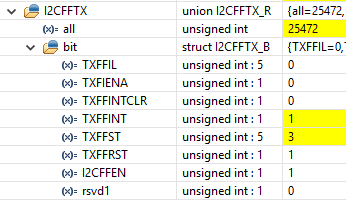
I2caRegs.I2CFFTX.all = 0x6000; // Enable FIFO mode and TXFIFO
return;
}
void I2C_write_new()
{
Uint16 i = 0;
// Setup slave address
I2caRegs.I2CSAR = 0x60;
while (I2caRegs.I2CSTR.bit.BB == 1)
{
i = 1;
}
I2caRegs.I2CCNT = 3;
I2caRegs.I2CDXR = 0x60;
I2caRegs.I2CDXR = 0x66;
I2caRegs.I2CDXR = 0x60;
I2caRegs.I2CMDR.bit.TRX = 1; //Set to Transmit mode
I2caRegs.I2CMDR.bit.STP = 1; //Master must release bus once Tx is complete , i.e. I2CCNT =0
I2caRegs.I2CMDR.bit.MST = 1; //Set to Master mode
I2caRegs.I2CMDR.bit.FREE = 1; //Debugger will not halt the bus on a breakpoint
I2caRegs.I2CMDR.bit.STT = 1; //Send the start bit, transmission will follow
// Send start as master transmitter
// I2caRegs.I2CMDR.all = 0x6E20;
}
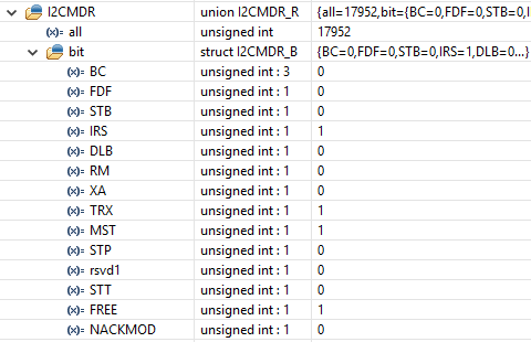
I have attached the I2CMDR register settings before and after sending i2c data.
Before->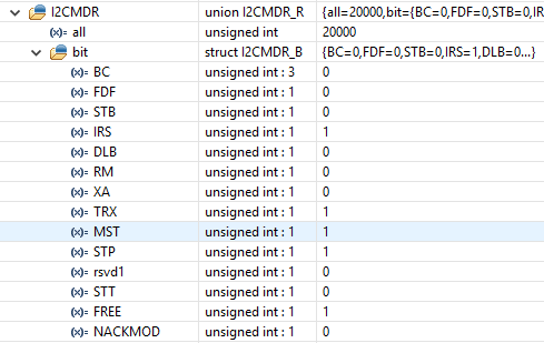 After->