This thread has been locked.

If you have a related question, please click the "Ask a related question" button in the top right corner. The newly created question will be automatically linked to this question.

TMS320F28379D: Triggering CLA Task by ECAP

Part Number: TMS320F28379D
Other Parts Discussed in Thread: CONTROLSUITE

Hello everyone,

I am trying to trigger a cla Task by an ecap Interrupt. My ADC Interrupts are triggering the cla just fine but I don't know what I am doing wrong in the configuration of the ecap/cla.

Here is my CLA Interrupt configuration.

static inline void Init_CLA_Interrupt(void)
{
   EALLOW;

   // Soft Reset of the CLA - After a soft reset you must wait at least 1 SYSCLKOUT cycle before reconfiguring the MIER bits.
   Cla1Regs.MCTL.bit.SOFTRESET = ON;

   // Configuration of CLA1TASKSRCSELLOCK Registers not necessary, Task are only assigned once

   // Set triggers to CLA Tasks
   // AdcDrv assigns Adc Interrupts(max 4 per adc) to different adc channels (16 per adc)
   DmaClaSrcSelRegs.CLA1TASKSRCSEL1.bit.TASK1 = CLA_TRIG_ECAP5INT;      
   DmaClaSrcSelRegs.CLA1TASKSRCSEL1.bit.TASK2 = CLA_TRIG_ADCAINT1;      
   DmaClaSrcSelRegs.CLA1TASKSRCSEL1.bit.TASK3 = CLA_TRIG_ADCDINT1;      
   DmaClaSrcSelRegs.CLA1TASKSRCSEL1.bit.TASK4 = CLA_TRIG_EPWM2INT;      
   DmaClaSrcSelRegs.CLA1TASKSRCSEL2.bit.TASK5 = CLA_TRIG_SD1INT;        
   DmaClaSrcSelRegs.CLA1TASKSRCSEL2.bit.TASK8 = CLA_TRIG_NOPERPH;       

   // Set pointers for the CLA Tasks
   Cla1Regs.MVECT1 = (UL)(Cla1Task1);
   Cla1Regs.MVECT2 = (UL)(Cla1Task2);
   Cla1Regs.MVECT3 = (UL)(Cla1Task3);
   Cla1Regs.MVECT4 = (UL)(Cla1Task4);
   Cla1Regs.MVECT5 = (UL)(Cla1Task5);
   Cla1Regs.MVECT8 = (UL)(Cla1Task8);

   // Set Interrupt Enable for all 8 CLA Tasks
   Cla1Regs.MIER.all = 0xFF;

   EDIS;

   EALLOW;

   // clear all old interrupt flags
   Cla1Regs.MICLR.all = 0xFF;
   // clear old Overflow flags
   Cla1Regs.MICLROVF.all = 0xFF;

   // Configure the vectors for the end-of-task interrupt for all tasks
   PieVectTable.CLA1_1_INT   = endOfClaResetTask1Isr;
   PieVectTable.CLA1_2_INT   = endOfClaIsr;
   PieVectTable.CLA1_3_INT   = endOfClaIsr;
   PieVectTable.CLA1_4_INT   = endOfClaResetIsr;
   PieVectTable.CLA1_5_INT   = endOfClaIsr;
   PieVectTable.CLA1_8_INT   = endOfClaInitIsr;

   // Enable CLA interrupts at the group and subgroup levels
   PieCtrlRegs.PIEIER11.all  = 0xFFFF;  // enable all interrupts in group 11
   IER |= (M_INT11 );                   // enable group 11

   // cla accesses interrupts directly, not through pie (c2000 cla faq)
   // Enable CLA interrupts at the group and subgroup levels for ecap
   //PieCtrlRegs.PIEIER4.all  = 0xFFFF;  // enable all interrupts in group 4
   //IER |= (M_INT4 );                   // enable group 4

   EDIS;

   EALLOW;

   // Initialize CLA Variables through a software interrupt to CLA task 8
   Cla1Regs.MIFRC.bit.INT8 = ON;
   asm("  RPT #3 || NOP");
   while(Cla1Regs.MIRUN.bit.INT8 == 1);

   EDIS;
}

And here is my ecap configuration.

void Init_CaptureDrv(void)
{
    US module = (US) ECAP_DRV_MODULE_1;
    UL period = 0U;

    EALLOW;
//    ///////////////////////////////////////////////////////
//    //APWM
//    ///////////////////////////////////////////////////////
//    // Pinmux configuration GPIO25 => J6 pin 51; OUTPUTXBAR2
//    OutputXbarRegs.OUTPUT2MUX0TO15CFG.bit.MUX8   = 3U;      // MUX8 => ECAP5OUT
//    OutputXbarRegs.OUTPUT2MUXENABLE.bit.MUX8     = ON;
//    ///////////////////////////////////////////////////////
//    //eCAP
//    ///////////////////////////////////////////////////////
//    // GPIO95 => J5 pin 42
//    GpioCtrlRegs.GPCPUD.bit.GPIO95 = OFF; //pull up enabled
//    GpioCtrlRegs.GPCDIR.bit.GPIO95 = OFF; //input
//    InputXbarRegs.INPUT7SELECT = 95U;
//    InputXbarRegs.INPUTSELECTLOCK.bit.INPUT7SELECT = OFF;   //register is not locked

    // Shadow registers
    UL sRegCTRPHS           = 0x00000000;       // Shadow Register Counter phase
    UL sRegCAPx             = 0x00000000;       // Shadow Register CAPx
    US sRegECEINT           = 0x0000;           // Shadow Register Interrupt Enable (EALLOW)
    US sRegECFLG            = 0x0000;           // Shadow Register Interrupt Flag
    US sRegECCLR            = 0x0000;           // Shadow Register Interrupt Clear
    US sRegECFRC            = 0x0000;           // Shadow Register Interrupt Force

    for(module = (US) ECAP_DRV_MODULE_1; module <= (US) ECAP_DRV_MODULE_4; module++)
    {
        // configure as capture
        eCapDrv.pRegsECAP[module]->ECCTL2.bit.CAP_APWM  = OFF;

        // Disable CAP1-CAP4 register loads and  make sure the counter is stopped
        eCapDrv.pRegsECAP[module]->ECCTL1.bit.CAPLDEN    = OFF;
        eCapDrv.pRegsECAP[module]->ECCTL2.bit.TSCTRSTOP  = OFF;

        // set counter phase to 0
        eCapDrv.pRegsECAP[module]->CTRPHS    = sRegCTRPHS;

        // initialize eCap Registers to 0
        eCapDrv.pRegsECAP[module]->CAP1  = sRegCAPx;

        // disable interrupts and clear flags
        eCapDrv.pRegsECAP[module]->ECEINT.all    = sRegECEINT;
        eCapDrv.pRegsECAP[module]->ECFLG.all     = sRegECFLG;
        eCapDrv.pRegsECAP[module]->ECCLR.all     = sRegECCLR;
        eCapDrv.pRegsECAP[module]->ECFRC.all     = sRegECFRC;

        // Two rising and two falling edges to determine period and duty cycle
        eCapDrv.pRegsECAP[module]->ECCTL1.bit.FREE_SOFT  = 3U;           // TSCTR is free running
        eCapDrv.pRegsECAP[module]->ECCTL1.bit.CAP1POL    = OFF;          // Rising Edge
        eCapDrv.pRegsECAP[module]->ECCTL1.bit.CAP2POL    = ON;           // Falling Edge
        eCapDrv.pRegsECAP[module]->ECCTL1.bit.CAP3POL    = OFF;          // Rising Edge
        eCapDrv.pRegsECAP[module]->ECCTL1.bit.CAP4POL    = ON;           // Falling Edge
        eCapDrv.pRegsECAP[module]->ECCTL1.bit.CTRRST1    = ON;           // Difference operation
        eCapDrv.pRegsECAP[module]->ECCTL1.bit.CTRRST2    = ON;           // Difference operation
        eCapDrv.pRegsECAP[module]->ECCTL1.bit.CTRRST3    = ON;           // Difference operation
        eCapDrv.pRegsECAP[module]->ECCTL1.bit.CTRRST4    = ON;           // Difference operation
        eCapDrv.pRegsECAP[module]->ECCTL1.bit.PRESCALE   = OFF;          // Use no prescaler

        // Synchronization
        eCapDrv.pRegsECAP[module]->ECCTL2.bit.SYNCI_EN       = ON;           // Enable sync in
        eCapDrv.pRegsECAP[module]->ECCTL2.bit.SYNCO_SEL      = OFF;          // Sync in is passed through to sync out
        eCapDrv.pRegsECAP[module]->ECCTL1.bit.CAPLDEN        = ON;           // Enable capture units
        eCapDrv.pRegsECAP[module]->ECCTL2.bit.TSCTRSTOP      = ON;           // Start Counter
        eCapDrv.pRegsECAP[module]->ECCTL2.bit.REARM          = ON;           // Arm one-shot
        eCapDrv.pRegsECAP[module]->ECCTL2.bit.CONT_ONESHT    = OFF;          // Continuous operation mode
    }

    // Configure APWM
    period = (UL)CLKDRV_SYSCLKOUT__MHZ / (UL)SDCLK_FREQ__MHZ;

    eCapDrv.pRegsECAP[ECAP_DRV_MODULE_5]->ECCTL2.bit.CAP_APWM       = ON;               // eCap5 works as APWM
    eCapDrv.pRegsECAP[ECAP_DRV_MODULE_5]->ECCTL2.bit.SYNCI_EN       = OFF;              // Disable sync-in option
    eCapDrv.pRegsECAP[ECAP_DRV_MODULE_5]->ECCTL2.bit.SYNCO_SEL      = 3U;               // Disable sync out signal
    eCapDrv.pRegsECAP[ECAP_DRV_MODULE_5]->CAP1                      = (period - 1U);    // UL set period value
    eCapDrv.pRegsECAP[ECAP_DRV_MODULE_5]->CAP2                      = (period/2U - 1U); // UL set compare value
    eCapDrv.pRegsECAP[ECAP_DRV_MODULE_5]->CAP3                      = (period - 1U);    // UL set period value
    eCapDrv.pRegsECAP[ECAP_DRV_MODULE_5]->CAP4                      = (period/2U - 1U); // UL set compare value
    eCapDrv.pRegsECAP[ECAP_DRV_MODULE_5]->ECCLR.all                 = 0xFF;             // Clear pending __interrupts.
    eCapDrv.pRegsECAP[ECAP_DRV_MODULE_5]->ECCTL1.bit.FREE_SOFT      = 3U;               // TSCTR counter is unaffected by emulation suspend (Run Free)
    eCapDrv.pRegsECAP[ECAP_DRV_MODULE_5]->ECCTL1.bit.PRESCALE       = OFF;              // No prescale
    eCapDrv.pRegsECAP[ECAP_DRV_MODULE_5]->ECCTL2.bit.TSCTRSTOP      = ON;               // Time Stamp Counter free running

    //DEBUG
    eCapDrv.pRegsECAP[ECAP_DRV_MODULE_5]->ECEINT.bit.CTR_EQ_PRD     = ON;               // Interrupt on CTR = PRD


    EDIS;                           // Enable write protection
}

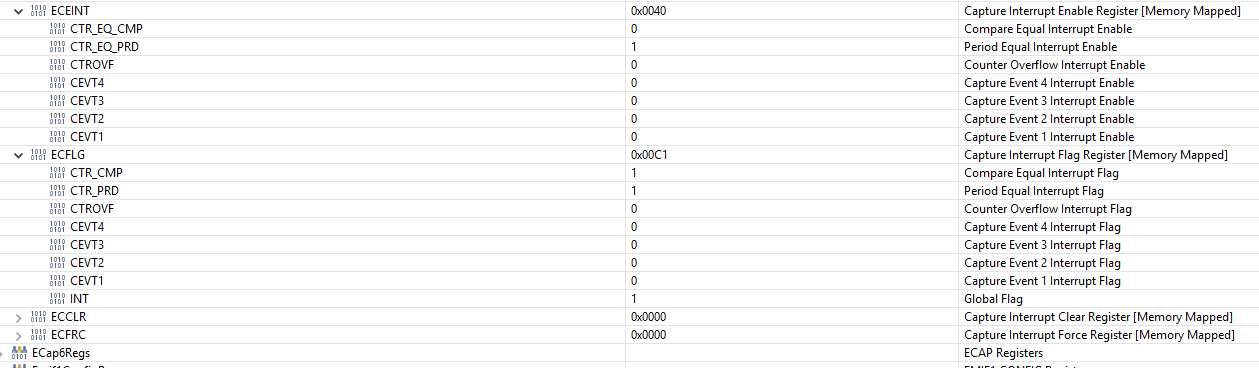
The flag indicating the Interrupt is popping up:

I also found in the c2000 faq that the cla Interrupts do not go through the pie instead they can trigger the Task directly. I don't see this happening. Any help is appreciated!

Thanks!

Alex


  • Alex,

    Can you detail steps you have taken to debug?  Such as:

    • - Does task 8, initialization task, work correctly and complete (.. making sure the C28x isn't stuck waiting forever...)?
    • - Put a breakpoint in the CLA task 1 to see if it is hit. also check that an unexpected breakpoint in task 1 isn't set and stopping execution. 
    • - Does the CLA interrupt flag get set for task 1?
    • - Confirm the vector value is correct for task 1?  Double check that other registers are set correctly.
    • - I notice at one point you are clearing "old CLA interrupt flags" make sure the eCAP interrupt isn't getting clobbered by this (check the order of setup is correct)

    I suggest watching the CLA hands-on-workshop.  It is very good at describing the CLA, how to develop code for it, and also how to debug it in Code Composer Studio. I think you will find it helpful in debugging cases like this.

    Here is the link to the CLA workshop:

    Click here for more CLA FAQs and resources.

    I hope this helps. If this resolves your issue, please click the green "This resolved my issue" button to let me know. 

    Regards,

    Lori

  • Hi,

    I have set a __mdebugstop(); in my cla task 1 and 8. The task 8 gets entered and runs through properly. As do my Adc triggered cla tasks, I can see it in the end of tasks interrupts  that I configured. But the task 1 never gets entered.

    I also don't see the Cla1Regs.MIFR bit getting set for the task 8 and also don't see the MIRUN getting set. As I showed you yesterday my eCap fires an interrupt on the CTR=PRD Event and this interrupt is enabled. I think there is a link missing between the interrupt and the start of the task.

    The MVECT value in the Register is the same as the oone in my .cla file and my value which  I am assigning the MVECT Register to. 

    For the configuration of the tasks triggered by the adc I used the C2000 controlsuite examples, but I could not find any for triggering a cla task by other peripherals. Could you maybe provide a simple configuration to trigger a cla task by any peripheral other than the adc? I watched the hands on tutorial but I just don't see what I am missing.

    Thanks!

  • Alex,

    Thanks for the feedback.  I will take a closer look and get back with you by end of Friday. 

    The methodology for connecting the eCAP is the same to that of the ePWM and ADC.  You are correct, the interrupt from the peripheral goes directly to the CLA and does not depend on the PIE. 

    Regards

    Lori

  • Hi,

    thank you for your reply.

    Today I started some small projects only to trigger a cla task through an epwm and an ecap. The good News is it worked out. The bad one is I compared the Cla1Regs Task Vector and MIER bits, the DmaClaSrcSelRegs for the Right Interrupt numbers , the Interrupt enables and flags in the peripheries (ecap, epwm). I do not see a difference. What other Register should I take a look at? Which register is taking part in transmitting the Interrupt to the cla?

    Thanks 

    Alex

  • Alex,

    A debug suggestion - disable the interrupts for the ePWM and ADC.  See if you observe any difference.  I understand your eCAP interrupt is the highest priority so it shouldn't be blocked but reducing the things going on in the code may help.  

    I put together a quick minimal test.  The interrupts are forced in this example.

        DisableDog();
        DINT;
    
        EALLOW;
        CpuSysRegs.PCLKCR0.bit.CLA1 = 1;
        CpuSysRegs.PCLKCR3.bit.ECAP5 = 1;
    
        MemCfgRegs.LSxMSEL.bit.MSEL_LS4 = 1;
        MemCfgRegs.LSxCLAPGM.bit.CLAPGM_LS4 = 1;
        MemCfgRegs.LSxMSEL.bit.MSEL_LS5 = 1;
        MemCfgRegs.LSxCLAPGM.bit.CLAPGM_LS5 = 1;
    
        Cla1Regs.MVECT1 = (uint16_t)(&Cla1Task1);
        Cla1Regs.MIER.all = (M_INT1);
        DmaClaSrcSelRegs.CLA1TASKSRCSEL1.bit.TASK1 = CLA_TRIG_ECAP5INT;
        EDIS;
    
        ECap5Regs.ECCTL2.bit.CAP_APWM = 1;      // Enable APWM mode
        ECap5Regs.ECCTL2.bit.TSCTRSTOP = 0;     // Stop the timer - for this example we will force INT
        ECap5Regs.ECCLR.all = 0x0FF;            // Clear pending interrupts
        ECap5Regs.ECEINT.bit.CTR_EQ_PRD = 1;    // enable Compare Equal PRD interrupt
    
        // force the eCAP5 PRD interrupt 4 times
        ECap5Regs.ECFRC.bit.CTR_PRD = 1;     // force interrupt
        asm("  RPT #7 || NOP");              // wait for CLA to start
        while(Cla1Regs.MIRUN.bit.INT1 == 1); // wait for CLA to finish
    
        ECap5Regs.ECFRC.bit.CTR_PRD = 1;     // force interrupt
        asm("  RPT #7 || NOP");              // wait for CLA to start
        while(Cla1Regs.MIRUN.bit.INT1 == 1); // wait for CLA to finish
    
        ECap5Regs.ECFRC.bit.CTR_PRD = 1;         // force interrupt
        asm("  RPT #7 || NOP");              // wait for CLA to start
        while(Cla1Regs.MIRUN.bit.INT1 == 1); // wait for CLA to finish
    
        ECap5Regs.ECFRC.bit.CTR_PRD = 1;         // force interrupt
        asm("  RPT #7 || NOP");              // wait for CLA to start
        while(Cla1Regs.MIRUN.bit.INT1 == 1); // wait for CLA to finish
        ESTOP0;

    CLA Code:

    _Cla1Task1:
         MADDF32 MR0, MR0, #0x3F80  ; increment MR0 by 1
         MMOVXI MR1, #0x00FF
         MMOV16 @0x5098, MR1 ; clear eCAP5 interrupt flags
         MNOP
         MNOP
         MNOP
         MSTOP
         MNOP
         MNOP
         MNOP
    _Cla1T1End:

  • Thank you for your assistance!

    I finally figured it out. In my bigger application the initialization of my peripherals was done in the very beginning of my initialization routine. The initialization of the cla was done a little bit later. To quote the TRM:

    For example, task 1 (MVECT1) can be set to trigger on EPWMINT1 by writing 36 to
    DmaClaSrcSelRegs.CLA1TASKSRCSEL1.bit.TASK1. To disable the triggering of a task by a
    peripheral, the user must set the DmaClaSrcSelRegs.CLA1TASKSRCSELx[TASKx] bit field to 0. It
    should be noted that a CLA task only triggers on a level transition (an edge) of the configured interrupt
    source.

    The last sentence is the clue. I just needed to reset the Interrupt flags fo the peripherals.

  • Alex,

    Thank you for letting me know what the resolution was.  Yes the CLA has to see the edge; if the interrupt is already pending it will be lost.  I will add this as one of our CLA FAQs.

    Happy coding & Regards

    Lori