This thread has been locked.

If you have a related question, please click the "Ask a related question" button in the top right corner. The newly created question will be automatically linked to this question.

TMS320F28379D: TMS320F28379D ADC, Matlab,

Part Number: TMS320F28379D

Hi everyone,

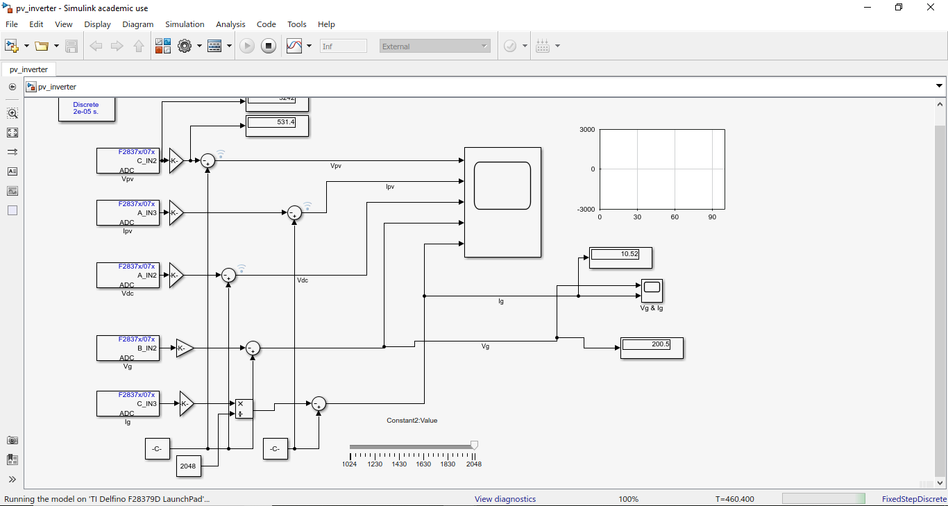
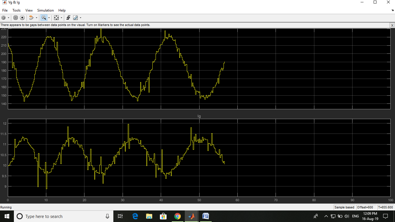
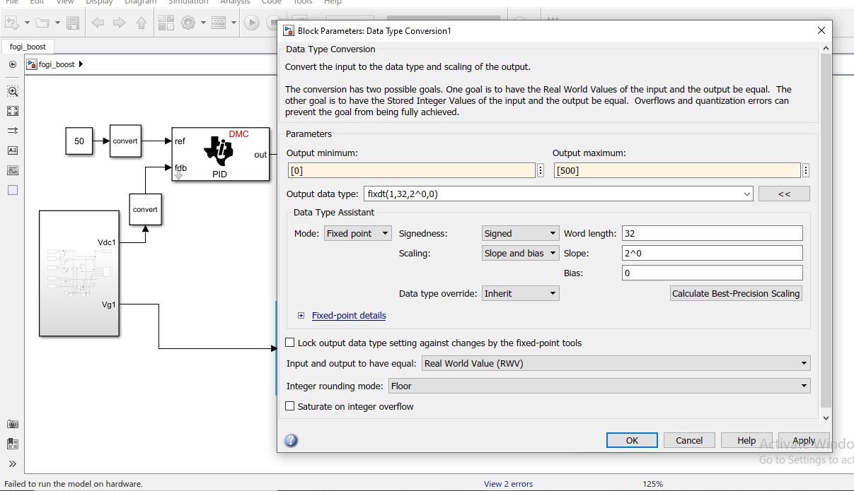
I am working with Development Kit TMS320F28379D with Matlab 2018a and code composer studio 8.1.0 to generate code and direct implement on target. I have a problem while working on real time implementation for signal extraction from ADC of this kit. In ADC setting, sampling time is set as defined sampling time (Ts= 20μs) model is terminate after some time in external mode, while sample time is replaced by inherent sample time = -1. Then system is run for long time, but problem is that actual signal frequency is 50Hz but from scope it does not meet its frequency. Please suggest me what is mistake is going on by me and provide me solutions.

I have another doubt about hardware interrupt block is it required or not for implement real time implementations (In external mode) please suggested me.

  • Hi Penendra,

    I'm not sure what is the issue is here. 50Hz should be fine,and you should see clean signals at that rate. 

    The HW interrupt block is not required to run an algorithm in real-time on the C2000.

    Probably best for you to contact MathWorks Tech Support (and provide them you model) so they can help investigate.

    Thanks,

    -Brian

  • Hi pemendra,

    Here is a post which talks about improving the performance of the external mode by tuning the serial baud rate.

  • Thank You Venkatesh Sir,

    While increasing baud rate as described in given link, Simulink model is failed to run on Target hardware,

    Whenever set baud rate (SCI_A) 5e6 bit/second and increasing the sampling time then waveform on scope is proper and correct but problem is again arises after 400 to 450 second Simulink model has terminated.

    I have another problem while using PI controller for close loop operation, I am trying two ways to connect PI controller   

    1.  First one by creating own PI controller using Gain and discrete integrator, then code is properly generated and model is run for long time but output of ADC as well as any block of model has zero always. Why its output is zero please 

    2. Second Way is done by using C28X DMC library PID controller then error is come out which is given as,

    Error due to multiple causes.

    Caused by:

    • The input must have a 32-bit signed fixed-point data type with power-of-two slope and zero bias.
    • The input fraction length has to be between 1 and 29 (inclusive).

    To solve this problem data type converter block is used with following setting (also attached setting of data type converter in Figure),

    Output minimum [0] and output maximum [500]

    Output data type: fixdt(1,32,2^0,0)

    Data type assistant

    Model: fixed point

    But occurring error is given as;

    ### Generating code into build folder: D:\Hardware\fogi_boost_ert_rtw

    ### Build procedure for model: 'fogi_boost' aborted due to an error.

    The input fraction length has to be between 1 and 29 (inclusive).

    Component:Simulink | Category:Model error

    An error occurred while propagating data type 'int32' from 'fogi_boost/PID Controller/In1', output port 1.

    Please provide the solution for developed close loop operation using PI controller using embedded coder support library in matlab

  • Hi,

    Please connect to us at:

    https://www.mathworks.com/support/contact_us.html

    We can get some expert to look in to the problem on PID.