This thread has been locked.
If you have a related question, please click the "Ask a related question" button in the top right corner. The newly created question will be automatically linked to this question.
Hello guys,
I have another issue with my project.
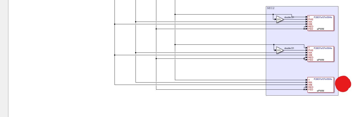
So the basic idea is to generate 9 PWM signals and control the Frequency, Phaseshift (between the PWM Signals) and the Deadband time over a GUI.
Theoretically it do what I want, but when I change the Frequency multiple time, some PWM signals don't work anymore and only giving an straight High or Low signal out.
The error apears sporadically and not all PWM Signals are affected.
I have no clue what it could be. Also have tried it on another TMS320F28379D Launchpad.
I have uploaded my project with the GUI.
Best regards
Kevin
Hi Kevin,
Is it possible that you can isolate the issue by scaling down your model.
Work on a single PWM module and try to reproduce the behavior.
You can then import the code in CCS and debug. Here is how you can create a CCS project from MATLAB/Simulink.
So I scaling down my program, but i must have 2 PWM signals.
It must have something to do with the "Synchronization action" i'm setting it on "Set counter to phase value specified via input port".
When I disable this option, so the PWM signal has no phaseshift, it works fine...
But I need the phaseshift between the signals.
Here is the generated ccs project.PWM_3PHASE_DAB_TEST_ert_rtw.7z
Hi Kevin,
Unfortunately you need to debug your model. But if you can pass the Frequency values at which this behavior can be reproduced and if you can provide a list of PWM signals that are affected, we can pitch in. But we need a scaled down model where we can reproduce the issue.
Few points that can help.
1. Try to calculate the period and other count values when problem occurs.
2. Try to feed the same values through constant block in a different model.
3. See if these values are blocking the PWM operation.
4. Analyzing those data points can help understand the underlying issue.
HTH,
Hi,
the thing is that I can't name precise frequencys, the effect apears at all frequencys ( tested between 1 and 250 khz)
With constant values is it no problem.
When I debug the model and switching the frequency, some PWM signals aren't working anymore.
Sometime they're apearing again, when i'm again switching to another frequency and also stay when i'm switching back to theprevious frequency. disapears
But most of the time the signals don't come back.
So it's completely random. Don't seeing a pattern.
Three PWM signals are stable and aren't affected. Marked this in the screenshot.
It must have something to do with the Counter value settig at the synchronization.
Best regards
Kevin
precise
Hello Venkatesh,
I changed the EPWM clock divider to SYSCLKOUT/2, but I still have the same issue.
Hi Kevin,
I could simulate the problem. However when I debugged using the CCS the values for TBPRD, CMPA and CMPB for the slave PWM matched that of Master. Hence we cannot suspect that these values are getting corrupted. I also observed the TBCTR of the Slave PWM is running which indicates the PWM module is ticking but no output. As noted by you, the pattern is random. We are looking for clue from TI what settings if present/missing could cause this behavior. That can help in investigating. I will ask them to look in to this issue.
Hello Venkatesh,
thank you for your effort.
I'm hoping you guys find a solution for this issue. It would really help me out.
Best regards
Kevin
Hi,
When you are dealing with variable frequency applications, if the updates to Period and Compare values are not made appropriately and counter can go out of sync. There are several posts related to this already and I suspect that is the problem in your case as well.
Please refer to this to start with.
https://e2e.ti.com/support/microcontrollers/c2000/f/171/t/317898