This thread has been locked.

If you have a related question, please click the "Ask a related question" button in the top right corner. The newly created question will be automatically linked to this question.

LAUNCHXL-F28379D: Not receiving data over I2C

Part Number: LAUNCHXL-F28379D
Other Parts Discussed in Thread: C2000WARE, TMS320F28379D,

Hi All,

Using the i2c_ex1_loopback example code, I'm not seeing how to receive data over I2C.

In loopback mode, the code operates as advertised.  When I take it out of loopback mode, I don't see how it's getting data from the I2C receive buffer.  I don't know if data is getting into the buffer.

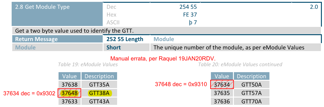
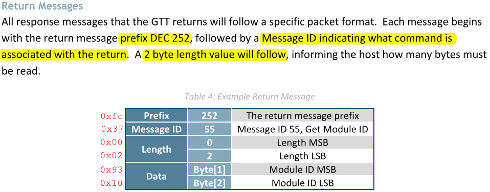
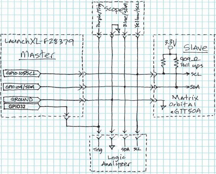
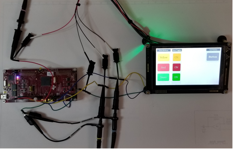
Sending commands is not problem.  I'm connected to a display, and all commands I send it are responding as expected, except for values that should be returning over I2C.

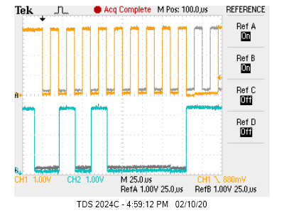
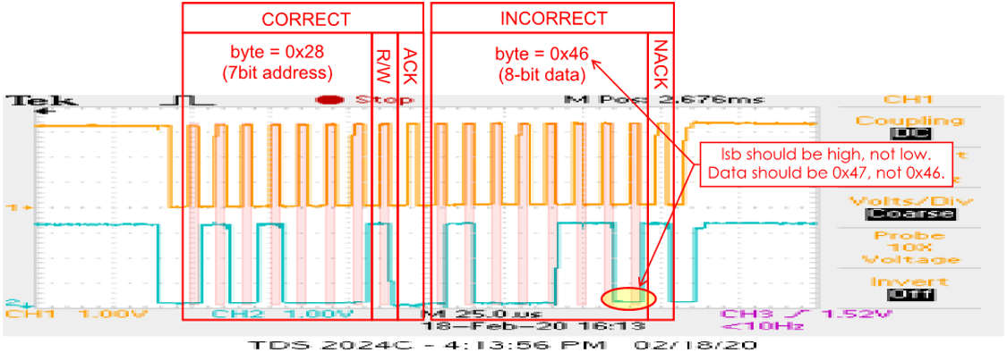
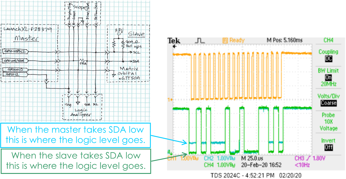
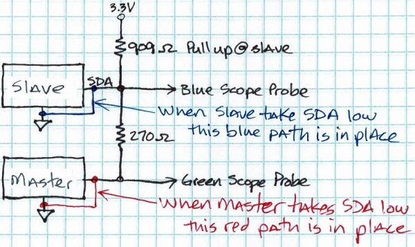
I'm getting the FIFO receive interrupts, so I thought I was getting data from the I2C bus, but all it ever presents is 0x00.

I know the display is working properly, because I have some Arduino example code that it's working with.

Here are my changes to the receive part of the ISR to grab a single byte of data:

//
// I2C A Transmit & Receive FIFO ISR.
//
 __interrupt void i2cFIFOISR(void)
{
    uint16_t i;

    //
    // If receive FIFO interrupt flag is set, read data
    //
    if((I2C_getInterruptStatus(I2CA_BASE) & I2C_INT_RXFF) != 0)
    {
        uint16_t bytes_Received;

        bytes_Received = I2C_getRxFIFOStatus(I2CA_BASE);

        for(i = 0; i < 1; i++)
        {
            rData[i] = I2C_getData(I2CA_BASE);
            
            if(rData[i] != 0)
            {
                bytes_Received = bytes_Received + 1;
                bytes_Received = bytes_Received - 1;
            }
            DEVICE_DELAY_US(10);
        }

        //
        // Clear interrupt flag
        //
        I2C_clearInterruptStatus(I2CA_BASE, I2C_INT_RXFF);

        Example_PassCount++;
    }

What I see coming in is a copy of what I'm sending out.  The DLB bit is cleared, so I don't think the I2CDRR register is getting the outgoing data loaded internally.  Here's the register setup:

I suspect I'm not getting the registers setup properly.  Let me know what you'd like to see, and I'll gladly oblige.

Can you please point me in the right direction?

Thanks, 

robin

  • Robin,

    In digital loop back mode, data transmitted out of I2CDXR registers are directly received in I2CDRR register through internal path. Disabling DLB, you disconnect this path and will not receive the data transmitted on I2CDXR.

    If you're looking for an example code where you want to have two I2C talking to eachother like in real application, you need to use i2c_ex3_external_loopback example code available in

    Path:<C2000Ware>\driverlib\f2837xd\examples\cpu1\i2c

    Example project:i2c_ex3_external_loopback

    In this example code, you connect I2CA and I2CB externally

    Regards,

    Manoj

  • Thanks for the quick response Manoj.

    I understand that by disabling DLB, I2CDXR xmit data won't be internally passed into the I2CDRR.  But I thought the I2CDRR would pick up I2C bus responses from the peripheral display that it's communicating with.  I expected them to be passed into the FIFO receive buffer where they could be retrieved by my code.

    Sending a command from the MASTER_SEND_MODE TMS320F28379D to the display should trigger an I2C response from that display.  It's most likely causing that response to occur, but the I2C hardware/software of the TMS320F28379D doesn't seem to be picking it up.

    FIFO receive interrupts are occurring, but the data in the receive buffer is only ever one of two values:

    1. The value found in I2CDRR is the same value transmitted through the I2CDXR register (as if the DLB bit were set).
    2. Otherwise, it's always 0x00.  Even when I expect to see a response from the display.

    I will look over the i2c_ex3_external_loopback example code again.  Maybe I'll find some configuration there that doesn't exist in my modified version of the I2c_ex1_loopback example.

    I'd greatly appreciate it if you could help me understand the flow of how a slave response is received by the I2C port on the TMS320F28379D.  There are a lot of configuration options, and I suspect I may have overlooked (or misunderstood) one or more settings.

    All help is very much appreciated.

    robin

  • Robin,

    Have you tried probing I2C bus? Do you see any valid data on it? Also, what display are you trying to interface with I2C?

    Regards,

    Manoj

  • If possible please share logic analyzer (or) oscilloscope snapshots?

    Regards,

    Manoj

  • Hi Minoj,

    The display is eGTT50A from Matrix Orbital.  It has an I2C interface that only carries commands from the MCU master (in this case the TMS320F28379D) to the slave (eGTT50A), and responses from the slave display back to the master MCU.  All the heavy lifting regarding drawing graphics and text, and deciphering touch screen operations are handled inside the display module.  In the grand scheme of things, there is very little communication between the two.

    From the Matrix Orbital manual, here's the MCU master's request for a value embedded in the display's registers that indicate the module type: (0x28-write 0xfe 0x37)

    And here's the expected response from the slave display to that request for module type: (0x28-read 0xfc 0x37 0x00 0x02 0x93 0x10)

    Here's a scope image of clock and data signals:  (appx. 50kHz clock rate)

    Here are logic analyzer images of the correctly working, complete transaction on the Arduino connected system:  (I2c address = 0x28)

    Here are the logic analyzer images of the failing transaction on the TMS320F28379D system:

    The TMS320F28379D receives 0x00 into its I2CDRR ad infinitum.

    I ran the i2c_ex3_external_loopback example code and found similar results.  The unmodified code runs without failing, seemingly because the I2CDRR is filling with the data being put out through the I2CDXR register.  Once I break that connection, and rely on the I2CDRR pulling slave data written on the I2C bus, the system stops receiving anything but 0x00.

    I suppose I'm just missing a crucial piece of the puzzle, but I've read documentation over and over again, and I'm not seeing it.

    Thanks for your help.

  • UPDATE

    Hi Minoj,

    After manipulating the I2C register configuration and where and when I pull data from the I2CDRR, I'm now receiving the data that the slave is transmitting.

    However, the data being captured from the I2CDRR is losing its lsb.  The lsb is there, but it's always zero.  The data being transmitted through the I2CDXR is perfect.  There's no lsb issue with transmitted data.

    I see the following in logic analyzer displays and by capturing I2CDRR bytes
    in a buffer:
    1. All the bytes transmitted by the master are being picked up by the display, perfectly.
    2. All the bytes transmitted by the display are being picked up by the master, but imperfectly.
    1. It seems as though each byte has its lsb zeroed out.
    2. Like how it would treat a 7bit address.  The 8th (read/write) bit is ignored rather than being 
      interpreted as part of the address.
    3. As if the received data were right shifted one bit and then left shifted one bit.

    I know these results would lead one to believe the problem lies with the display sending the errant data, but the system works perfectly when using an Arduino Uno as the MCU instead of the TMS320F28379D.

    I'm hoping this explanation will spark some new thoughts.  Do you have any suggestions on what to check next?

    Thanks, 

    robin

  • Robin,

    1) Check whether I2CMDR.BC bitfield is configured 0 (or) 7? This I2CMDR.BC bit field control the number of bits to be transmitted (or) received by the I2C module.

    I2CMDR.BC = 0 corresponds to 8 bits / data packet

    I2CMDR.BC = 7 corresponds to 7 bits / data packet.

    2)Are you waiting for Receive-data-ready interrupt bit (I2CSTR.RRDY = 1) to be set before reading I2CDRR register?

    3) Is your logic analyzer reading your data packet (including LSB bits correctly bit correctly?

    4) Possibility of VIL / VIH / rise time violation. Though highly unlikely would suggest you to check rise time? If your rise time is slow. Check the following:

    • Lower your pull-up resistors on SCL / SDA pair.Having higher pull-up resistor on SCL / SDA pair will affect rise time
    • If you have series protection resistors on I2C bus (for better noise immunity), it can affect the margin you have on VIL limits and could potentially cause missing bits
    • Try running I2C bus at lower speed

    Regards,

    Manoj

  • Incorrectly pressed "TI thinks resolved". Don't worry this thread is still considered open

  • Hi Manoj,

    Thanks for your response.

    1. I2CMDR.BC is and has been set to 0 (meaning 8 bits)
    2. I'm not waiting for RRDY to be set.  Could it be that I'm grabbing the data before it is complete?  Seems less likely, because the data received is 100% consistent.  I'll try setting up a wait.
    3. The logic analyzer shows the incoming data to always have the lsb = 0.  This is evidence that the problematic data is originating with the slave.  Tech support at Matrix Orbital says that the problem can't be with the display module not only because of this, but also because the display works correctly when using an Arduino with their example code.
    4. I experienced a rise-time issue early on and corrected it with appropriate pull up resistors.  You can see in scope images previously attached in this thread that clock and data signals are pretty crisp.
    5. I've tried running I2C bus speeds from 25kHz up till it stops working at about 500kHz.

    I've forwarded my modified version of i2c_ex1_loopback example code to Matrix Orbital, but I don't know how much they can help.  They're not familiar with the C2000 series, and it's doubtful they'll be willing to spend significant time learning about the TMS320F28379D.

    Thanks,

    robin

  • Robin,

    C2000 I2Cs support only upto 400 KHz. Is everything working around 400 KHz?

    Regards,

    Manoj

  • Did you try running I2C at 400 KHz? Is everything working as expected at 400 KHz?

    Regards,

    Manoj

  • Hi Manoj,

    I made a new discovery.

    Here’s what we already knew:

    The lsb of each data byte was being mysteriously zeroed out. Here’s the series of I2C commands and replies that were expected versus what appeared in logic analyzer readouts:

    Command: (Query Module Type)
    0x28 W - 0xfe - 0x37

    Expected Response:
    0x28 R – 0xfc – 0x37 – 0x00 – 0x02 – 0x93 – 0x10

    Actual Response:
    0x28 R – 0xfc – 0x36 – 0x00 – 0x02 – 0x92 – 0x10


    To corroborate the lsb theory, I sent this Command: (Query Module String)
    0x28 W - 0xfe - 0x38

    Expected Response:
    0x28 R – 0xfc – 0x38 – 0x00 – 0x06 – 0x47 – 0x54 – 0x54 – 0x35 – 0x30 – 0x41

    Actual Response:
    0x28 R – 0xfc – 0x38 – 0x00 – 0x06 – 0x46 – 0x54 – 0x54 – 0x34 – 0x30 – 0x40


    I sent other commands, all having the same problem of returning the lsb as zero. I’m convinced this phenomenon is consistent. I define it as: all data bytes being returned by the slave device will have zero at the lsb.  Address bytes are not affected, only data bytes are affected.

    Here are a couple of scope traces that zoom in on one of those erroneous data bytes: (should be 0x47, not 0x46)


    And zoomed in further on the data byte:


    And here’s the logic analyzer readout of the same byte:


    Here’s what’s new:

    I noticed that the lsb wasn’t being held as close to zero as the other bits in the returned data byte. I suspected it was because the MCU was taking it low, not the display. By adding a resistor in series with the data line (SDA), we’re able to see that the TI MCU (TMS320F28379D) is in fact taking SDA low during the lsb of the data byte.  Since this data byte is being returned by the display, the MCU should be hands-off until the NACK has occurred.

    I added a resistor in series with SDA, so I could determine precisely which device was taking the data line low.  Here’s where I added the resistor:


    Following is an image of scope traces. The blue trace is taken from the display side of the resistor, and the green trace is taken from the MCU side. The pullup resistors are at the display end of the I2C bus. Clearly, the MCU is driving SDA low, as is evidenced by the line not going as near ground in the blue trace. Here it is:

    Finally:

    So, the question is: “Why is the TI TMS320F28379D MCU taking the data line (SDA) low during the least significant bit of the data byte that is being returned by the display?”

    It’s not because of the I2CMDR.BC setting. It’s always been set to zero, which means 8bits (not 7bits).

    It’s not a problem with I2C clock speed. I now have the MCU clocking the SCL at ~113kHz. The display default speed is 115.2kHz. Anyway, the same problem exists at any reasonable speed.

    I’m using the fifo receive interrupt to determine when to copy the I2CDRR contents. The transmit interrupt is disabled. I’m not waiting for the RRDY to be set. (Let me know if you think this could be a problem.)

    I don’t think it’s an SCL or SDA rise-time issue. As seen in the scope images, the edges are pretty crisp. Here are close-up images: (fall-times are shorter)


    SDA rise-time is ~46ns and SCL is ~38ns. SPRS880K spec’s max timing requirements as 300ns:


    I appreciate your help.

    Thanks,
    robin

  • Robin,

    I'm not sure. But, my guess is the problem is because of the minor timing difference between I2C slave (115 KHz) and I2C master (113 KHz). Can make sure to have both I2C master and slave are working at the same frequency?

    Regards,

    Manoj

  • Hi Manoj,

    With I2C, clock speed is determined by the master.  The slave will use the master's clock signal to clock in data.  Speed matching is not necessary.

    Here's a link with more info.

    Thanks,
    robin

  • Robin,

    Well, unfortunately I have run of ideas what could be the possible reasons why this can happen without active hardware  / scope infront me. I wouldn't doubt F28379D.I2C as this peripheral has been used by many of customer over the years without any issues.

    Regards,

    Manoj

  • Still need help.

  • Have you already tried running them at same speed (100 KHz) as suggested in previous post. I think it is worth a try.

    Regards,

    Manoj

  • Hi Manoj,

    Yes, I dialed in the I2C clock to produce 115.2kHz, but exactly the same problem exists.

    This is good:

    All data is being transmitted by the F28379 perfectly, and the display is receiving it perfectly.

    This is bad:

    However, the F28379 is taking SDA low during the lsb of all data bytes received from the display.

    Again, in different words, all data transmitted by the slave display is being corrupted by the F28379. 

    The F28379 is interfering with the display's control of SDA by taking SDA low during the lsb of the display's data. 

    The F28379 doesn't interfere with the display's address response, but it does interfere with all of the display's data responses.

    Here's the image again, with some new info added in blue:

    Please let me know if you don't completely understand the exact symptoms.  I have it well defined, and am able to explain it further if needed.

    I have no doubt that the TMS320F28379D is well capable of communicating properly over I2C.  I don't fully understand all the various register settings and their effects.  I need help from someone fluent in these operations.  No doubt, I have something setup wrong.  I'm using a fifo interrupt to determine when incoming data is available.  I'm not using an interrupt for outgoing data.

    Do you have a LaunchXL-F28379D and a peripheral device to communicate with?  If you do, I'm happy to send you the code that I modified from the i2c_ex1_loopback example.  

    I'm also available via Skype to go through code and share screen images of code, logic analyzer, scope, etc..

    I'm quickly approaching a deadline, and am feeling pressure to make progress.  Please help.

    Thanks,
    robin

  • Robin,

    Can you provide some insight into your hardware setup?

    • Do you use series resistor on your bus? If so, how much?
    • Pull-up resistor values and where is it placed? Pulled up to 3.3v?
    • A good simplied diagram about your setup will be helpful?

    How have you configured GPIO pins for I2C? Please provide configuration details?

    You can send across the modified example code. I can take a brief look into and see whether I see any glaring mistake.

    Regards,

    Manoj

  • Based on your description, it looks like you're having a problem when I2C is configured as master receiver. I want confirmation that display isn't pulling the LSB low. To do that, configure SDA pin as GPIO input pin before enter I2C master receiver mode. This way, F28379D.I2C pin doesn't control the SDA pin. If the LSB is pulled low, it is the display and not F28379D I2C.

    Regards,

    Manoj

  • Hi Manoj,

    There is no series resistor on SCL or SDA lines. 

    There is one each 909 Ohm resistor pulling up to 3.3V on SCL and SDA at the slave end.

    Here's a quick scheme:

    Here's an image of my bench setup:

    I2C ports assigned in the example code (GPIO32 and 33) aren't exposed to the user on the LaunchXL-F28379.  I assigned GPIO 104 and 105 instead.  Here's the assignment:

        //
        // Initialize GPIOs 104 and 105 for use as SDA A and SCL A respectively
        //
        GPIO_setPinConfig(GPIO_104_SDAA);
        GPIO_setPadConfig(104, GPIO_PIN_TYPE_PULLUP);
        GPIO_setQualificationMode(104, GPIO_QUAL_ASYNC);
    
        GPIO_setPinConfig(GPIO_105_SCLA);
        GPIO_setPadConfig(105, GPIO_PIN_TYPE_PULLUP);
        GPIO_setQualificationMode(105, GPIO_QUAL_ASYNC);
    

    Code to follow...

    Thanks,
    robin

  • Hi Manoj,

    Attached is my modified i2c_ex1_loopback example code.

    I tried adding code to change the SDA pin to a GPIO input during reads, but I can't get that to work.  If it's not receiving data, it's not generating ACKs.  Without ACKs, the data stream ends abruptly.

    Instead I took another look at bus levels with a resistor in series with the SDA line.  I'm very convinced it is the f28379 that is taking the SDA line low.  Here's another look at it:

    Here's how it works:

    Scenario 1:  Slave takes SDA to logic zero

    The BLUE connection is made and the voltage level where the blue scope probe is connected goes to zero.  The voltage level on the green scope probe goes to zero as well, because there's no pullup resistor at the master end of the bus.

    Scenario 2:  Master takes SDA to logic zero

    The RED connection is made and the voltage level where the green scope probe is connected goes to zero.  The voltage level on the blue scope probe is a bit above zero, due to the voltage divider caused by the 270 Ohm resistor in series with the 909 Ohm pullup resistor. 

    You would expect the voltage at the blue probe to be: 

    (270 / (270 + 909)) * 3.3V = 756mV

    As can be seen in the image above, the difference between the green and blue scope traces is pretty close to 756mV.

    This is pretty conclusive.  If you want me to further experiment with it, let me know what you'd like to see.

    I'm hoping you'll see something wrong with the attached code.

    Thanks,
    robin

  • Hi Manoj,

    It's been a long day (month), and I'm a little loopy, but I think I found the problem.

    In initialization, I set the I2COAR register to the same address as the slave.

    I'll take a closer look in the morning, but I'm pretty sure that's it.

    I'll let you know what I find out.

    Thanks,
    robin

  • Okay. Please let us know.

    Regards,

    Manoj

  • Hi Manoj,

    I've confirmed the final issue with my bidirectional I2C communications was that I had inadvertently assigned the same I2C address to both the master and slave.

    As a result, responses from the slave (display) were being interfered with by unwanted responses from the master.

    Thanks for your patient assistance.

    robin