This thread has been locked.

If you have a related question, please click the "Ask a related question" button in the top right corner. The newly created question will be automatically linked to this question.

CCS/TMDSHVRESLLCKIT: How to get the value of FEM

Part Number: TMDSHVRESLLCKIT
Other Parts Discussed in Thread: CONTROLSUITE, TIDM-02002

Tool/software: Code Composer Studio

After the initialization (source code:D:\ti\controlSUITE\development_kits\TMDSHVRESLLCKIT_v1.0\HVLLC), PWM work work as show below:

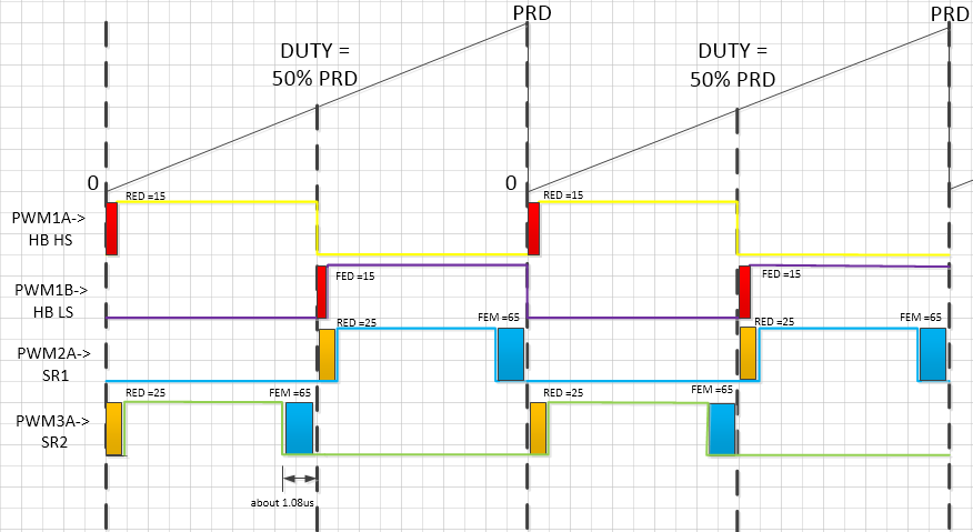
SR PWM will turn off about 1.08us before HS when FEM = 65. 

The trip zone configuration  forces the SR signal on anytime the SR current is greater than the value of DACVAL.

// Configure ePWM Trip-Zone module
EPwm2Regs.TZCTL.bit.DCAEVT1 = TZ_FORCE_HI; // EPWM2A will go HIGH

EPwm3Regs.TZCTL.bit.DCAEVT1 = TZ_FORCE_HI; // EPWM3A will go HIGH

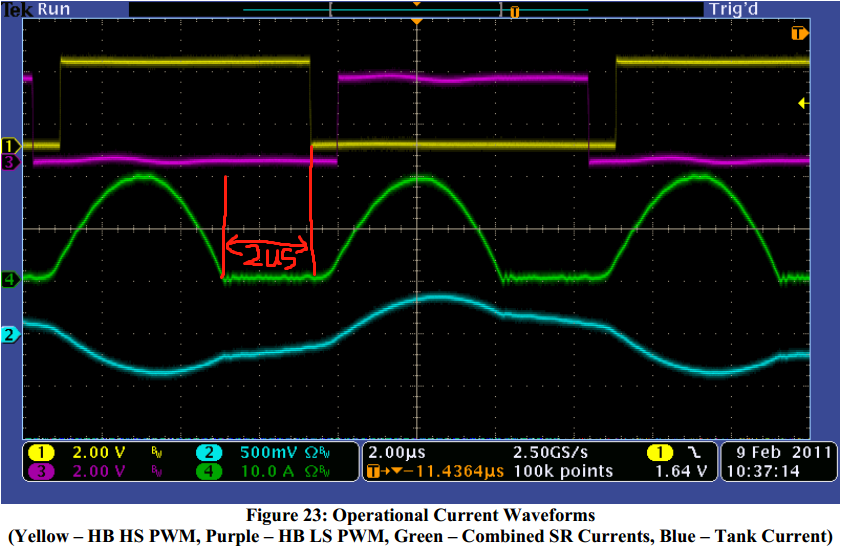
So,the time that SR PWM  turn off  before HS is less than 1.08us when FEM = 65. 

But ,the time which in the Figure23 of  "HVLLC-SWGuide.pdf" is abuot 2us.

I had noticed,the FEM CAN be changed by the GUI.


// assign GUI variable Textboxes to desired "setable" parameter addresses
varSetTxtList[0] = &Pgain;
varSetTxtList[1] = &Igain;
varSetTxtList[2] = &Dgain;
varSetTxtList[3] = &RED;
varSetTxtList[4] = &FED;
varSetTxtList[5] = &REM1;
varSetTxtList[6] = &FEM1;
varSetTxtList[7] = &REM2;
varSetTxtList[8] = &FEM2;
varSetTxtList[9] = &COMP1;
varSetTxtList[10] = &COMP2;


Maybe FEM is not equal to 65 in this case.
My questiones:
1) In a completed project, is FEM fixed or dynamically adjusted.
2) How to get the value of FEM (FEM = 65).

  • Hi Aiden,

    You're right, it doesn't look like FEM = 65 in Figure 23 of the user guide.

    1) My understanding for this reference design is that FEM is fixed, unless the user changes it. The user can change the value of FEM through the watch window in CCS. The user should be able to see how the switching waveforms change as the PWM values are changed.

    For example, in build 1 the SR signal timing depends on only the PWM counter:

    HVLLC-SWGuide, p.17 - Build 1

    15. Carefully adjust “Period” and verify that “Gui_Vout” increases when you decrease “Period” and
    that it decreases when you increase “Period”.
    16. Carefully adjust “RED” and “FED” to see how they affect the Half-Bridge PWM signals.
    17. Carefully adjust “REM{X}” and “FEM{X}” to see how they affect the Rectifier PWM signals.

    In build 3, the SR signal timing depends on the trip zone event and the PWM counter:

    HVLLC-SWGuide, p.22, 23 - Build 3

    14. On the oscilloscope, make a note of where the SR PWM signal’s falling edge is relative to where
    the SR Current drops back to 0.
    15. Set “Comp_Enable” to 1. Observe how the SR PWM signal’s falling edge has shifted. The SR
    PWM signal’s falling edge should now be closer to where the SR Current drops back to 0.
    16. Now experiment with changing the load. Notice that the SR PWM signal’s falling edge tracks
    where the SR Current drops back to 0.
    17. Now experiment with changing the “COMP{X}” value. This affects the current level at which the
    analog comparator will allow the SR PWM to turn-off.

    ...

    Note: The analog comparators is used to delay the SR PWM’s falling edge and will not advance the
    falling edge beyond that specified by “FEM{X}”.

    2) The default value assigned to FEM at initialization is 65 from the HVLLC-Settings.h file, but as you've pointed out, the value of FEM in figure 23 likely isn't equal to the default value. I don't see a description in the user guide that says what the conditions were when that figure was captured, so it was probably after the step instructing the user to "carefully adjust REM{x} and FEM{x} to see how they affect the Rectifier PWM signals", or even in build 3 with the comparator action active.

    If you find line 343 in the HVLLC-Main.c file and then you right click "FallingEdgeMargin1" and select "Open Declaration" (Keyboard shortcut F3), CCS will take you to the place where the default value is defined.

    When the code is running on the device, you can open the watch window and read/modify the value of FEM1, FEM2. You could also inspect the DBFED register of the PWM2, PWM3 to get the current value of FEM.

    Best,

    Clayton Greenbaum

  • Hi Greenbaum,

    Thank you for your reply.

    After I had collected and read the relevant information,I think the value of FEM is related to the resonance frequency of LLC. 

    The SR PWM should turn off at the points:

    SR and HS turn off at the same time         fsw   >= fo    ( fsw is PWM frequency ,fo is LLC resonance frequency )

    SR should turn off at To/2                             fsw   < fo      ( To is  LLC resonance period)

    I'm not really sure,I hope to find the LLC case and detailed instructions on the TI website. There's obviously no answer for me

    If you have time, you can read this article,it might solve my doubts. www.researchgate.net/.../325522715

    My English is not very good,I don't understand very well.

    In addition,I've been looking at tidm_02002 case recently. This case without current sensor in SR circuit, there should be some similarity in the turn off of SR. I didn't find the explanation in this list either.

  • Hi Aiden,

    Thanks for sharing that resource. I will try to look at that article and get back to you with some comments on how the FEM value should be chosen later this week, or early next week.

    Best,

    Clayton Greenbaum

  • Hi Aiden,

    Sorry for the delay in getting back to you. There's been a lot on my plate recently.

    You mentioned the TIDM-02002, it employs a similar comparator based method of turning off the SR switches: http://www.ti.com/lit/ug/tidueg2b/tidueg2b.pdf

    Figure 20 shows the secondary current sense circuit and how that feeds into the CMPSS. Figure 24 shows how the timing is generated for the SR control.

    In general, I think you'll be safe to set the FEM value in this TMDSHVRESLLCKIT design to To/2, and let the comparator control the exact turn-off timing of the SR PWM.

    I hope you're in good health,

    Clayton Greenbaum