This thread has been locked.

If you have a related question, please click the "Ask a related question" button in the top right corner. The newly created question will be automatically linked to this question.

LAUNCHXL-F28379D: DAC and ADC values are not same

Part Number: LAUNCHXL-F28379D

Hello,

I am using F28379D LaunchPad Development Kit for a project. I am competely new with this microcontroller programming.

I am design a circuit in the MATLAB simulink and run the design in the F28379D LaunchPad Development Kit.

I have generated the signal put it in the DAC pin and receivinging the same signal from ADC pin, connecting the DAC and ADC pins with a jumper wire physically.

But the real time ADC output is not the same.
I want to receive the same signal in the ADC.

Where should I change the values? and how can I modify my design for that?
I am attaching some snapshots of my design for clear view.

Thanks in Advance.

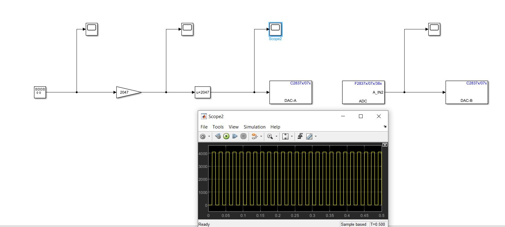
In the Above figure, this is the signal (scope 2) at DAC pin. The signal is square wave with 0 to 4096 values oscillation. 

In the Above figure, this is the signal (scope 3) at ADC pin output. This shows 0(zero) Values.

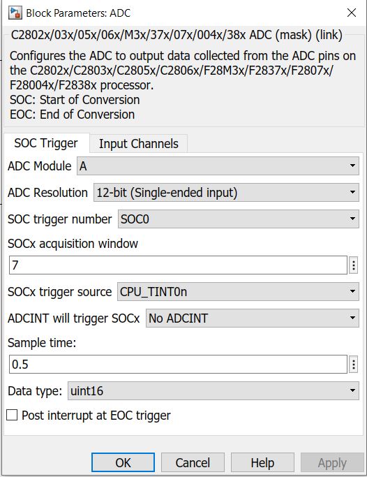
In the Above figure, this is my ADC parameter settings.

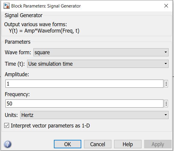
In the Above figure, this is the signal generator parameters.

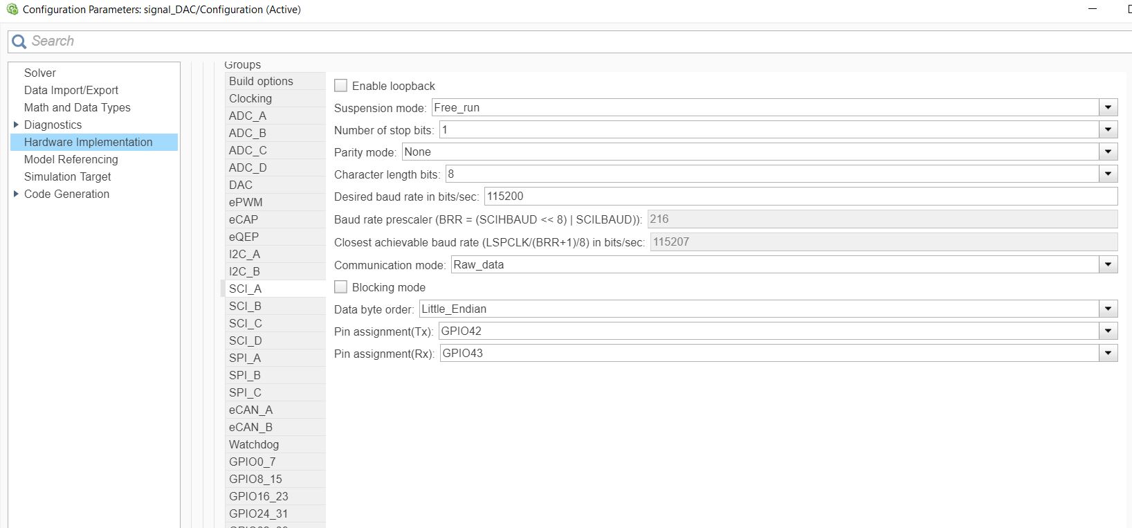
In the Above figure, this is the SCI_A baud rate.

In the Above figure, this is the external mode.

  • Fahad,

    Have you been able to confirm with a volt meter that the DAC value is indeed coming on the pin of the LaunchPad?  I'd like to make sure that this portion of the code is working correctly before we debug the ADC.

    Best,

    Matthew

  • Yes, the DAC output provides the same graph and same values.
    In the Oscilloscope , the maximum value is 3.3V shown as the corresponding value for the input of DAC is 4095.
    Shown in the figure below.

    I want to receive the same signal in ADC and see in the scope of the Simulink.
    I think, this portion of code is working correctly.
    please help me with the further portion of the code and the design.

    Thanks in advance.
    and sorry for the late reply.

  • Hi,

    One of the reasons why we see ADC return zero is the sample time mismatch between DAC and ADC.

    While the DAC is generating the square wave at 50Hz the ADC is configured to read the same at 2Hz (0.5 being the sample time in the ADC block).

    Another reason is ADC block used in polling mode does not guarantee the perfect synchronization with the DAC signal.

    The ADC block sampling of the input voltage it is not guaranteed if the sample is taken when the signal is low/high.

    So 2 approaches - ensure the DAC and ADC are in sync or ensure the sample times are consistent between the same.

    If you know the DAC output pattern, you can use an ePWM to generate the same pattern to trigger the ADC for conversion.

    Hope this helps,

  • Hi,

    Is your issue resolved? Can we close the issue?