Part Number: TMS320F28379D
Other Parts Discussed in Thread: ADS1203, ADS1202
I have some related questions about the SDFM:
I had in the past weird behavior of the SDFM. I'm using the module to monitor current sensors to fast switch off my device if a short circuit happens. For that I use the comparator unit inside with a low over sampling ratio and for normal measurement the SDFM.Data with a higher over sampling ratio.
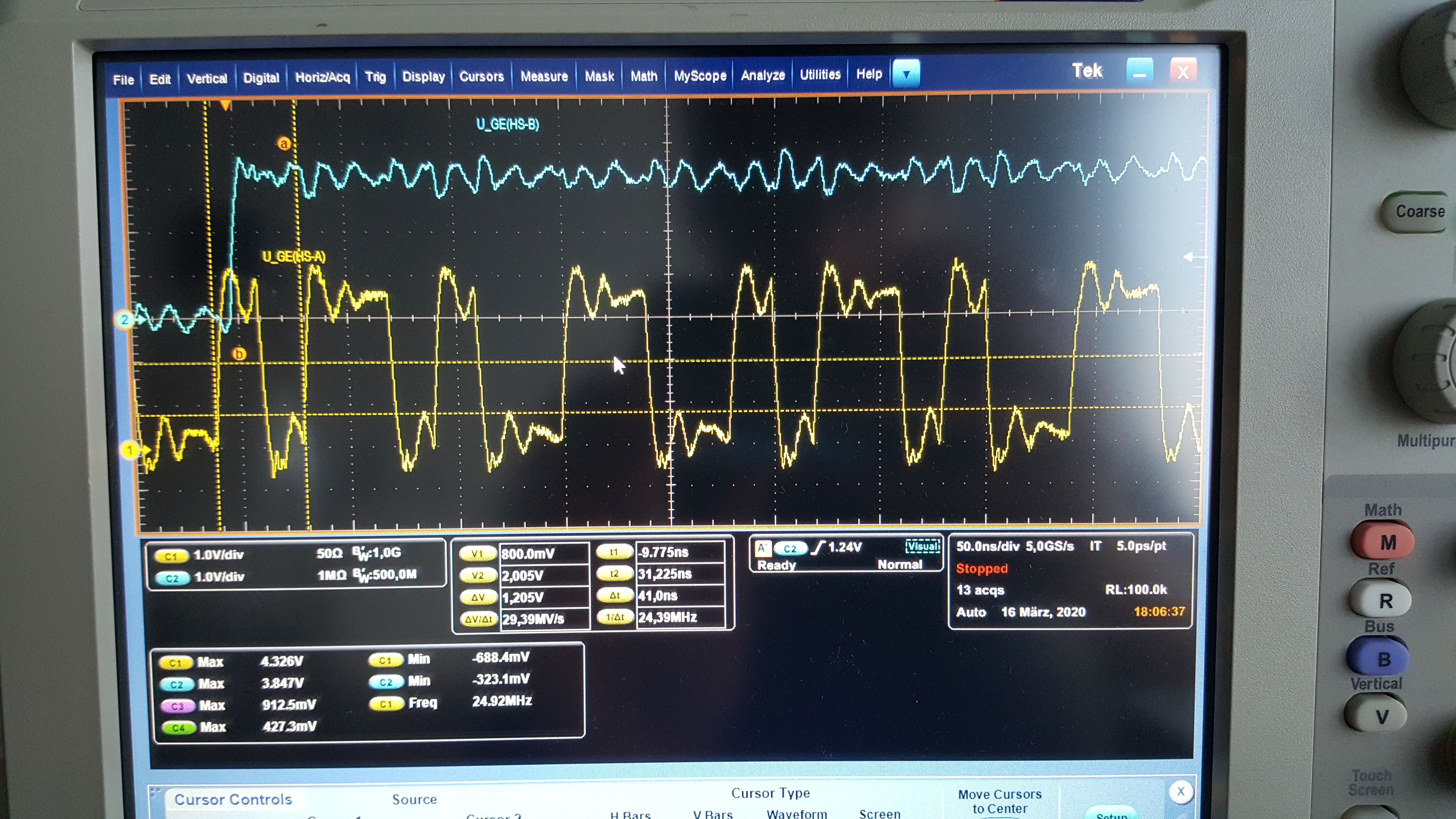
For the measurement I use separated PCBs with a Sigma Delta Modulator. Due to revisions I have different Sigma Delta Modulators in use (ADS1203, ADS1202, AMC1303E). During first setup I realized, that 10MHz Modulators will not work with TMS230, because it only supports 8...20*t_sysclk in its SDMF. So, I decided to lower the frequency of the TMS to 180MHz so it will also support the 10MHz Modulators.
By playing around with the boards, I noticed that the SDFM Comparator sometimes trips without any reason. This must be due to wrong synchronization of the SDFM.
To have a closer look to the problem, I programmed a FPGA to output a Manchester coded Sigma Delta stream and play with the parameters. To see if the SDFM lose synchronization I setup an interrupt every time it has new data available.
What I figured out is somehow strange. Running the TMS at exact 200Mhz it only supports data streams from 9.2 to 15.4Mhz. Everything beyond that will trigger the trip. But changing the frequency to 190 or even 210Mhz will make the SDFM support even higher frequencies. Changing the QSEL of the pin from async to sync will sometimes improve the behavior, but not always. It depends on the exact frequency of the data stream.
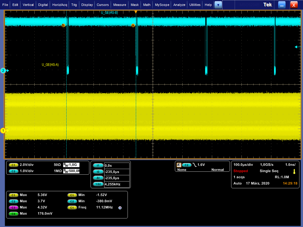
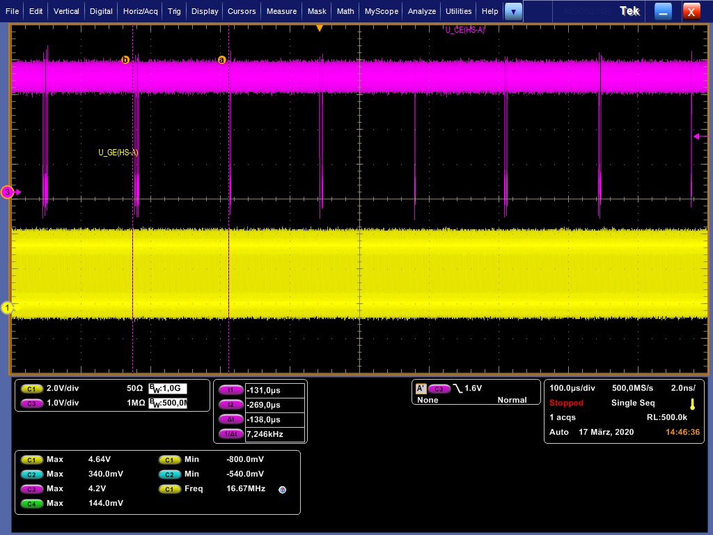
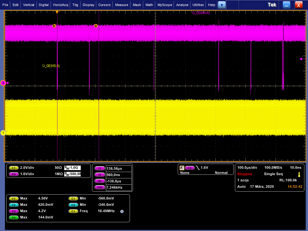
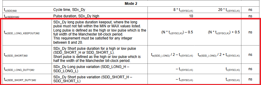
On the picture you see the sigma delta data stream on channel 1 and the toggle output of the TMS every time it has new data available.
I assume every time it takes longer to get a new value (blue lines on the DPX picture) it will get a wrong value.
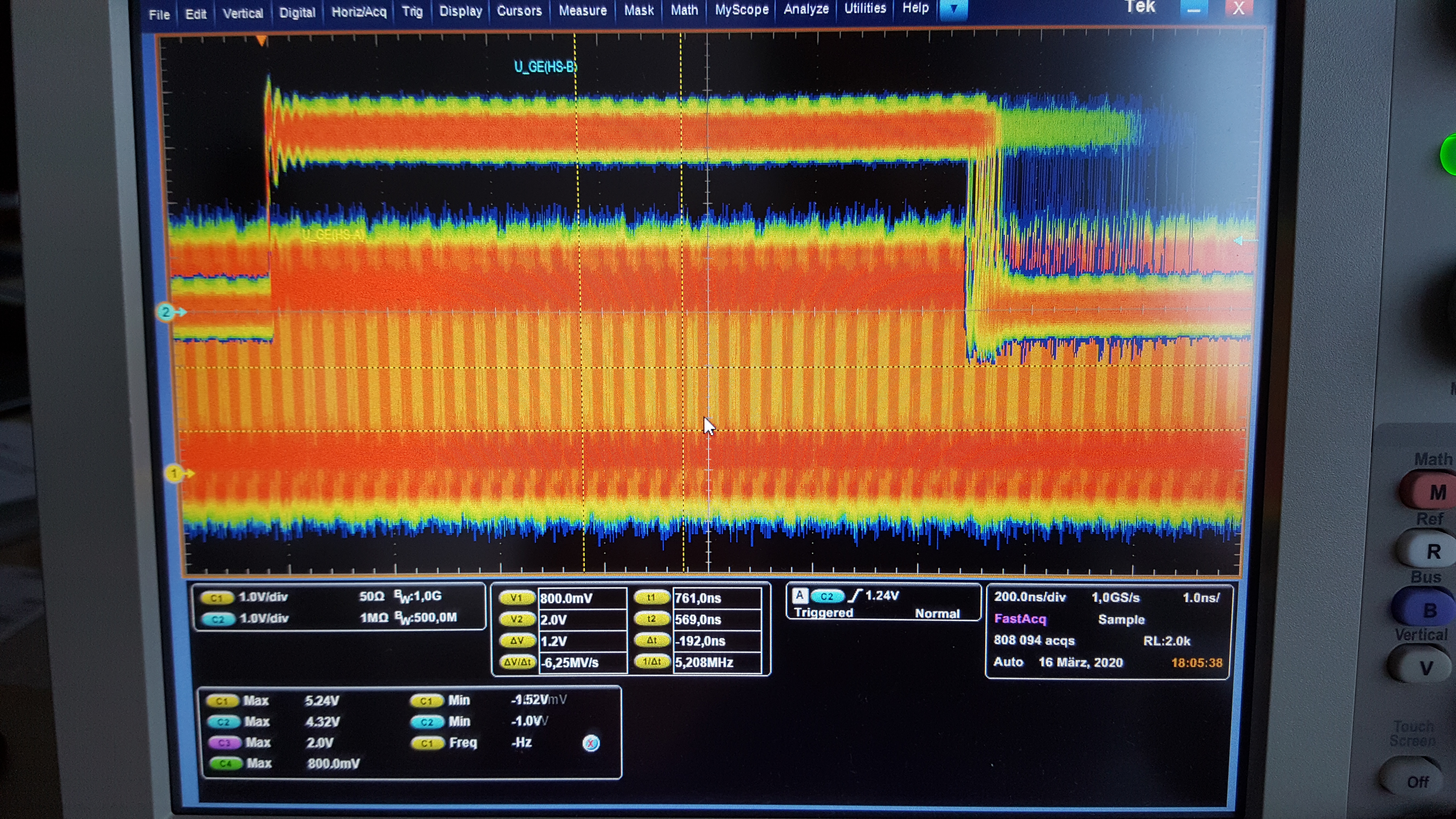
Because I use a fiber optic cable to transmit the data stream in my application, I also had a look on the difference times of high and low state, because usually the fiber optic cable will delay the rising edge a little.
What I realized, that if the delay of the edge is in the range of 10ns, doesn't matter what frequency the stream is running, it will corrupt the data.
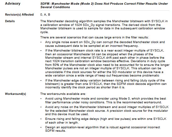
So, do you have a detailed description, how the SDFM is working and what constrains must be met? Why it is limitted to the frequency of 8...20*t_sysclk? Are you just oversampling the signal and what is the algorithm after the oversampling? Because the really short constrains of the technical reference manual are by fare not sufficient.
I'm talking specially about rise times, hold times, even a description of the implementation would be really useful. Because like this, I'm not able to use the TMS at all. And it would make more sense to me to use a FPGA.