This thread has been locked.

If you have a related question, please click the "Ask a related question" button in the top right corner. The newly created question will be automatically linked to this question.

DAC(H/L)VAL Trip event changes

Guru 56143 points
Part Number: LAUNCHXL-F280049C
Other Parts Discussed in Thread: BOOSTXL-DRV8320RS, MOTORWARE, INA240, TMS320F280049C

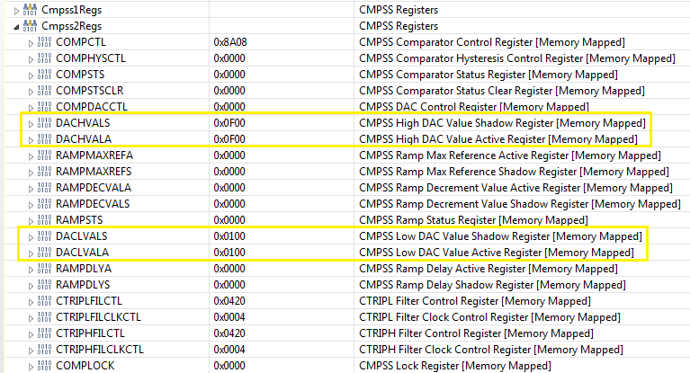
The debug register refresh DACHVAL DACHLVAL load value changes after a Trip zone event occurs and never reloads the init values.  I notice the DC filer sample clock value 0x100 (256) but not the DACLVALS 4048 and 0xF00 (3840) DACHVLA has changed the init value 0xFD0. This occurs on all 3 CMPSSx. The initial load values 0xFD0 are correct but only after MCU reset is forced via CCS debug.    

Any idea why CCS register DACH/L values are not reloading after a PWM trip event or why they are changing?  Perhaps this issue leads to frequent annoying low side DAC filter faults?

    // Set the initial value to half of ADC range
    uint16_t cmpsaDACH = 4048;//2048
    uint16_t cmpsaDACL = 4048;//2048

   // define these numbers in hal.h
   //
   CMPSS_setDACValueHigh(obj->cmpssHandle[cnt], cmpsaDACH);
   CMPSS_setDACValueLow(obj->cmpssHandle[cnt], cmpsaDACL);


  • The biggest problem being CMPSSx Fig.16-1 page 1690 does not have enough name identification to determine how the ePWM xBAR inputs Fig.18-49 Pg.1873 relate to or with table 18-3 MUX defines for each CMPSSx output. Does table 18-3 describe paths from the CMPSS or Boolean states? Seemingly they are events into xBAR input trip connectivity (Fig18-49) but how were Boolean states of the CMPSSx translated from MUX back to CMPSSx outputs?

    How can anyone know for sure how the output of the CMPSSx DACA/B relate to the MUX table entries as the names are different and far to vague to clarify a relationship exists. Only parts of the CMPSSx A/B output (names) relate but only to the MUX and ePWM input trip zone connectivity. Why are the MUX names not matching the CMPSSx output names to keep this translation clear to the designer?

    We need a table to clarify the nonsense dead ends in the way the CMPSSx outputs interconnect to the MUX events.  Without a proper table it is a game of Russian Roulette since the DC filters values are not happy with something in the event system become latching when they are defined as pass through filter flags CMPSS_TRIP_FILTER!

  • Someone at TI has shot themselves and many others in the proverbial foot! 

    Lab is05_motor_id.c has over written the HAL_setCMPSS's(void) settings that previously initialized. However the DACHVAL and DACHVAL in the motor.Vars.dac(a/b)Val were not set by anyone and over write above registers with odd count values. Where did the 0x100(256) originate was the question in my mind and why it messing with the Low side comparator DAC filter and trip latch events.

            //
            // set the reference value for internal DACA and DACB
            //
            HAL_setDACValue(halHandle, 0, motorVars.dacaVal);
            HAL_setDACValue(halHandle, 1, motorVars.dacbVal);
    
            //
            // set internal DAC value for on-chip comparator for current protection
            //
            {
                uint16_t  cmpssCnt;
    
                for(cmpssCnt = 0; cmpssCnt < HAL_NUM_CMPSS_CURRENT; cmpssCnt++)
                {
                    HAL_setCMPSSDACValueHigh(halHandle,
                                             cmpssCnt, motorVars.dacValH);
    
                    HAL_setCMPSSDACValueLow(halHandle,
                                            cmpssCnt, motorVars.dacValL);
                }
            }

  • The story has more pages and few extra DacValH/L that seem to overwrite above register (0x100).  HAL_setupCMPSSs() values should come from (user.h) but are missing in there too. So if you change the hal.c count values they get over written by some odd values. Don't be so surprised if you close your CCS debug register eye's and things get all buggy for no obvious reason.

  • /* Configure inverting input for internal COMPDAC(VDDA3v3) reference
             * and low comparator inverted Non-ASYNCH filter outputs  */
            CMPSS_configHighComparator(obj->cmpssHandle[cnt],
    					CMPSS_INSRC_DAC );
            CMPSS_configLowComparator(obj->cmpssHandle[cnt],
    					CMPSS_INSRC_DAC | CMPSS_INV_INVERTED);

    The low DAC can not be configured for inversion in this way as it remains latched and messes with the shadow values. Changing sign for the DACLVALS (int_16) seems to have fixed the CMPSS low latched tripped status and ePWM trip zone issue.

    Change of sign below for DACB load value ignores negative half cycle sine-wave needs to be inverse 2048 down to 0 counts. It would be nice to use signed integers for DACB and sample filter if the DAC(L/H)VALS register/s will allow such folly, the C+ array will.

        2048 + 1024 + 512 + 256, /* dacValH */              				
        2048 - 1024 - 512 - 256, /* dacValL */                 					
        2048, /* dacaVal */                                                    
        2048, /* dacbVal */  
        uint16_t  dacValH;
         int16_t  dacValL;
        uint16_t  dacaVal;
         int16_t  dacbVal;
    
        3848, /* dacValH */              					                    
        -3848, /* dacValL */                 					  
        3048, /* dacaVal */                                                 
        -3048, /* dacbVal */ 
    
        uint16_t cmpsaDACH = 3840;//2048
        int16_t cmpsaDACL = -3840;//2048


  • Seemingly the USER_ADC_FULL_SCALE_CURRENT_A should be set to mid supply of PGA_OUT, if it truly 1.65v for BoostXL-drv8320rs. SDK FOC adds user current offsets not described in SPRUHJ1H–January 2013–Revised June 2019.

    That said perhaps the negative offsets for IA (A,B,C) should be the bottom portion of ADC FS (0v - 1.65v) or 0-2048 counts. Anyway the motor ID calculation seems to work better via half user full scale current with the external current monitor. Setting the FS current for mV/A PP full scale of the external monitor produces odd time wait behaviors. The take away being signed integers for bidirectional current flow thresholds ADC mid supply.

    //! \brief Defines the maximum current at the AD converter
    //! BOARD_BSXL8320RS_REVA Gain=12 91mV/A, INA240 Gain=20 40mV/A(FS80A)
    #define USER_ADC_FULL_SCALE_CURRENT_A         ((float32_t)(80.00))

    // External current monitor set 40mV/A 
    //! \brief ADC current offsets for A, B, and C phases
    #define IA_OFFSET_A    (-40.0)   //~=0.5*USER_ADC_FULL_SCALE_CURRENT_A 
    #define IB_OFFSET_A    (-40.0)   //~=0.5*USER_ADC_FULL_SCALE_CURRENT_A 
    #define IC_OFFSET_A    (-40.0)   //~=0.5*USER_ADC_FULL_SCALE_CURRENT_A 
    
    // 0.005 = (-0.4) but 1/2 user full scale current
    // makes an unusually large offset value! 

  • Interesting the names were changed and look at the SDK (above post) and difference below shown SPRUHJ1H–January 2013–Revised June 2019.

    How could the offsets be so high in the SDK but not in the motor control suite?

    4.1.10 I_A_offset , I_B_offset , I_C_offset

    #define I_A_offset (0.8661925197)
    #define I_B_offset (0.8679816127)
    #define I_C_offset (0.8638074994)

    This module defines the ADC current offsets for A, B, and C phases. One-time hardware dependent, though the calibration can be done at run-time as well. After initial board calibration these values should be updated for your specific hardware so they are available after compile in the binary to be loaded to the controller.

  • What are your final questions? Seems like you have answered the questions you posted. I don't think there are the issues you mentioned above if you didn't change the example labs for TI's EVM kit.

    The SPRUHJ1H is for the motorWare, but the knowledge for FAST estimator and the definition of most parameters can be as a reference for motorControlSDK also.

    The offset values in use.h are just for the TI's EVM kit, you should change them according to the result from the offset calibration if you are using your own board. The calibration values are in the motorVars.offsets_I_A and motorVars.offsets_V_V for current and voltage.

  • The boostxl-drv8320rs PGA_OUT's I have confirmed to be centered 1.68v via the PGA filter outputs scope J5 - pin 45,46, 48 first removing the 300pF caps.

    Have confirm the user FS was oddly set 42A seemingly is not possible via 140mV/A input bias using the potentiometer rule to work the filter math. The best ADC 1/2 scale PTP current from 7mohm shunt (x12) gain is little less than 20 amps. Measured from ADC 2048 counts up to VDDA and from perfect 0 (1.68v) down to -2048 VSSA (0v).

    I noticed an immediate difference from the INA240 on our DC inverter amps to that of BoostXL current detection PGA amps. It seems the ADC current scale factor was set twice as high as the actual mV/A from filter. Without CMPSS to manage OVC DC trips there is only the boostXL Tz2 output to trip at peak current as configured. Obviously the SDK (FOC) did not have the DC source configured for ePWM trips, perhaps this was a WA to get NexFET peak 40A output but in some off hand obscure way. Otherwise the CMPSS DCA/B sources did not trip ePWM faults as they now do after adding in DC sources for Trip zone actions. 

    The input filter math: Vin * (R2/R1+R2) = 0.14028286141788452797730261667273 PGA_IN bias x 12 = 1.68v center PGA_OUT.

    User ADC full scale set to perfect 0v 2048 counts: 1.68v / 0.140mV/A = 24A Peak, not 42A. The 7mohm shunt (7mv/A) was factored out via PGA_IN bias x12 gain. Seemingly the best way to increase ADC +/- half scale (2048) counts is to reduce the shunt value from 7mohm to 3mohm to derive a 42A Peak FS? Seemingly the kit was limited to 24A peak when Boostxl-drv8320rs claims 40A peak drive current. This seems to explain why >10µH stator inductance rotor stalls at 20Hz when it should not. 

    Perhaps the SDK developers noticed this odd issue and further restricted the ADC 24A Peak?

    //! \brief Defines the maximum current at the AD converter
    //!        BOARD_BSXL8320RS_REVA Gain=12 84mV/A, INA240 Gain=20 40mV/A
    #define USER_ADC_FULL_SCALE_CURRENT_A         ((float32_t)(42.843))
  • Yanming Luo said:
    The SPRUHJ1H is for the motorWare, but the knowledge for FAST estimator and the definition of most parameters can be as a reference for motorControlSDK also.

    Oddly it refers to TMS320F280049c in several places and relates several crucial motor parameters that must be tweaked to get low inductance motors to even start motor ID process without stalling. If the R/L current is to low or to high will/can trip ePWP DCA/B triggered OSHT event faults when SDK is properly configured to fault as any production controller will have this fail safe. 

    Yanming Luo said:
    The offset values in use.h are just for the TI's EVM kit

    Right but that was set half and not 0.5% as seemingly should be configured, not (-21.428) in user.h. That is the point I'm making if these are only start values they are incorrect. It seems you are trying to say the(user.h) offset values are over written during motor ID process so they don't actually harm anything if set very high? 

    Yanming Luo said:
    you should change them according to the result from the offset calibration if you are using your own board.

    Yet _I_A was not stated in lab5  text but only to add _V_V into user.h offset values. Perhaps we should add both from lab5 motor ID no mater what inverter PCB? I may have lied and see I had //_I_A values taken from past motor ID. Yet was still 1/2 FS and not 0.005 (0.5%) as seemingly it should be according to older IQ bias offsets. Scope probe (Boostxl-DRV8320RS) has  -280mA offset, not 28.0A.

  • FYI:There seems to be -285mA offset viewed from scope probe (140mV/A) via PGA2,6,4_OF and configure PGA filters outputs J5 pin 45,46,48. This allows us to watch what the SDK is doing and how ADC scale factor relates to PGA input math formulas. We noticed the INA240 set 80A user ADC  FS and BoostXL set 42A user FS do not agree so much. And the user.h motor EST current parameters produce very high RS_Ohm values if the EST current was set to low, INA240 produced the same high RS (300ohms) as the BoostXL does if RS time wait to long and have to divide time wait for lower DC motor current. 

    So there is some discrepancy between the two input current monitor sources, TI should have a look as we did.  There should not be this much difference via ADC user SF as it relates to current measure source and precision of each as the motor current FS is exponentially increased. It seems to suffer the final motorVars.flux_VpHz being 62Hz when rotor is not stalled during state LC.

  • Gl said:
    And the user.h motor EST current parameters produce very high RS_Ohm values if the EST current was low. INA240 produced the same high RS (300ohms) as the BoostXL does if RS time wait to long and have to divide time wait for lower DC motor current. 

    Yet the INA240 40mV/A was much easier to determine time wait to get very accurate 1/2 LtoL RS ohms. Otherwise it detected high RS ohms if EST current was set to low. Finding RS ohms window with BoostXL seems more difficult via 7mohm shunts versus INA240 2mohm x20 gain!

    Again the DACA/B higher 3648 filter count (22Amps) is easily tripped via PGA's (140mV/A) versus INA240 (40mV/A) 80A FS. Seemingly 3.5mohm shunts may reduce random ePWM OC trips from USER_MOTOR_RES_EST_CURRENT_A values being on the edge. Oddly <5.2A seems to cause random trip issues for the DAC filter and boostXL.

  • As replied to another thread you posted, please make sure the settings of your own board are correct before you try lab05 and its subsequent labs. 

    https://e2e.ti.com/support/microcontrollers/c2000/f/171/t/891765