


Part Number: TMS320F28377D
Other Parts Discussed in Thread: C2000WARE
Hi:
when USE DB_ACTV_HIC to initial ePWM , a unexpected plus occur on EPWM1B when execute initial, the display as below:
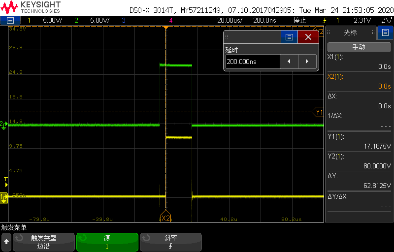
CH1: Trigger signal CH2:EPWM1B, EPWM1A is always low( do not display on scope)
the initial code:
EPwm1Regs.AQCTLA.bit.CAU = AQ_CLEAR;
EPwm1Regs.AQCTLA.bit.CAD = AQ_SET;
EPwm1Regs.AQCTLB.bit.CBU = AQ_CLEAR;
EPwm1Regs.AQCTLB.bit.CBD = AQ_SET;
EPwm1Regs.AQSFRC.bit.RLDCSF = 3; //The active register load immediately
EPwm1Regs.AQCSFRC.bit.CSFA = FORCE_LOW; //FORCE the EPWM2A output LOW
EPwm1Regs.AQCSFRC.bit.CSFB = FORCE_HIGH; //FORCE the EPWM2B output HIGH
EPwm1Regs.DBCTL.bit.IN_MODE = DBA_RED_DBB_FED; //EPWMxA In is the source for rising-edge delayed signal.
EPwm1Regs.DBCTL.bit.DEDB_MODE = 0;
EPwm1Regs.DBCTL.bit.POLSEL = DB_ACTV_HIC; //Active high complementary (AHC). EPWMxB is inverted.
EPwm1Regs.DBCTL.bit.OUT_MODE = DB_FULL_ENABLE; //Enable dead band time configuration
EPwm1Regs.DBCTL.bit.OUTSWAP = 0;
EPwm1Regs.DBRED.all = EPWM1_DBRED;
EPwm1Regs.DBFED.all = EPWM1_DBFED;
then change to DB_ACTV_HI, the display as below:

CH1: Trigger signal CH2:EPWM1B, EPWM1A is always low( do not display on scope)
the initial code:
EPwm1Regs.AQCTLA.bit.CAU = AQ_CLEAR;
EPwm1Regs.AQCTLA.bit.CAD = AQ_SET;
EPwm1Regs.AQCTLB.bit.CBU =AQ_SET ;
EPwm1Regs.AQCTLB.bit.CBD = AQ_CLEAR;
EPwm1Regs.AQSFRC.bit.RLDCSF = 3; //The active register load immediately
EPwm1Regs.AQCSFRC.bit.CSFA = FORCE_LOW; //FORCE the EPWM2A output LOW
EPwm1Regs.AQCSFRC.bit.CSFB = FORCE_LOW; //FORCE the EPWM2B output HIGH
EPwm1Regs.DBCTL.bit.IN_MODE = DBA_RED_DBB_FED; //EPWMxA In is the source for rising-edge delayed signal.
EPwm1Regs.DBCTL.bit.DEDB_MODE = 0;
EPwm1Regs.DBCTL.bit.POLSEL = DB_ACTV_HI; //Active high complementary (AHC). Neither EPWMxA nor EPWMxB is inverted (default).
EPwm1Regs.DBCTL.bit.OUT_MODE = DB_FULL_ENABLE; //Enable dead band time configuration
EPwm1Regs.DBCTL.bit.OUTSWAP = 0;
EPwm1Regs.DBRED.all = EPWM1_DBRED;
EPwm1Regs.DBFED.all = EPWM1_DBFED;
Between the two plans ,the first give EPWM1B force high then inverter in DBCTL[POLSEL], the second give EPWM1B force low then Neither EPWMxA nor EPWMxB isinverted in DBCTL[POLSEL].
The initial code is execute in sequence, the two plans should have same output on EPWM1B, why the fisrt have a 20us high pluse.
Addition information:
fpwm:20kHz
EPwm1Regs.CMPCTL.bit.SHDWAMODE = CC_SHADOW;
EPwm1Regs.CMPCTL.bit.SHDWBMODE = CC_SHADOW;
EPwm1Regs.CMPCTL.bit.LOADAMODE = CC_CTR_ZERO_PRD;
EPwm1Regs.CMPCTL.bit.LOADBMODE = CC_CTR_ZERO_PRD;
Thanks
