
- Ask a related questionWhat is a related question?A related question is a question created from another question. When the related question is created, it will be automatically linked to the original question.

Hi Everyone,
I’m setting up a TMS320F28069 as an I2C Slave, using “Example_2806xI2C_eeprom.c” as a starting point.
The TMS320F28069 is talking to a TMS320F28379, which is acting as master. It's running a version of “i2c_ex1_loopback.c”, which has been modified to transmit requests for data over I2C and act accordingly to slave responses.
In this phase of the project, I’m using a LaunchXL-F28069M and a LaunchXL-F28379D to develop the software before integrating it into the target product. The target product, which contains a TMS320F28069PNT, has been in production for several years, so this project is simply adding I2C communications to an existing product. Here's a picture of the development setup for a visual: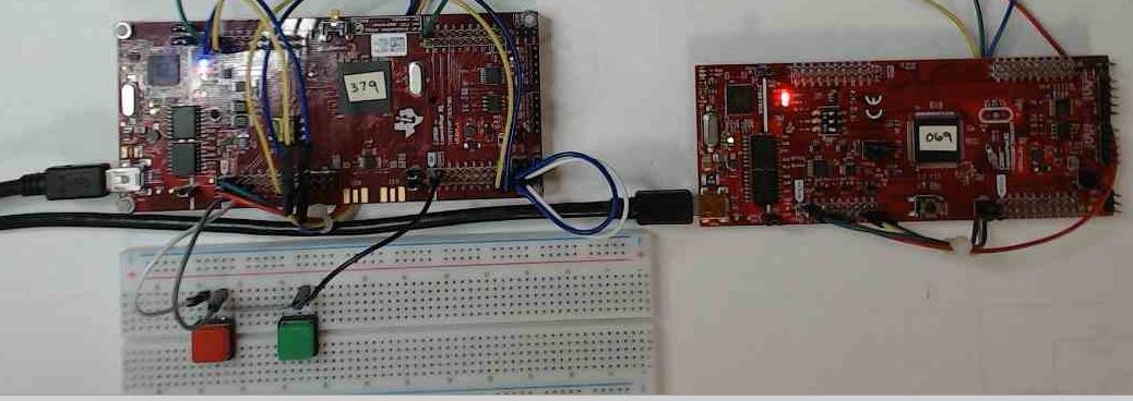
The extent of required communications is this:
This is all pretty simple in concept, but I’m having a hard time wrapping my mind around the on-board I2C hardware and example software.
At the moment, the master has two GPIOs configured as inputs, each having pull-ups and go low when corresponding buttons are pressed. When button 1 is pressed, the master transmits a request (0x01) that the slave interprets and responds with 4 data bytes (0x1a, 0x2b, 0x3c, & 0x4d). When button 2 is pressed (0x02), the slave responds with 4 different data bytes (0x5e, 0x6f, 0x7a, 0x8b). The transactions follow this sequence:
Then it immediately sends a dummy byte (without a stop condition):
Next, it sends a read command:
Here are logic analyzer images that show what I'm talking about:
When button 1 is pressed:

When button 2 is pressed:

Here is the master code running on the LaunchXL-F28379D:
//
// Included Files
//
#include "driverlib.h"
#include "device.h"

//
// Defines
//
#define MASTER_ADDRESS      0x29
#define SLAVE_ADDRESS       0x28

#define MICRO_SECONDS_10    5
#define MICRO_SECONDS_50    25
#define MICRO_SECONDS_100   50
#define MICRO_SECONDS_150   75
#define MICRO_SECONDS_200   100
#define MICRO_SECONDS_250   125
#define MICRO_SECONDS_300   150
#define MICRO_SECONDS_350   175
#define MICRO_SECONDS_400   200
#define MICRO_SECONDS_450   225
#define MICRO_SECONDS_500   250
#define MICRO_SECONDS_1500  750
#define MILLI_SECONDS_10    5000
#define MILLI_SECONDS_3500  1750000
#define MILLI_SECONDS_5000  2500000
#define SECONDS_7           3500000

#define SEND_1_BYTE         1
#define SEND_2_BYTES        2
#define SEND_3_BYTES        3
#define SEND_4_BYTES        4
#define SEND_5_BYTES        5
#define SEND_6_BYTES        6
#define SEND_7_BYTES        7
#define SEND_8_BYTES        8
#define SEND_9_BYTES        9
#define SEND_10_BYTES       10
#define SEND_11_BYTES       11
#define SEND_12_BYTES       12
#define SEND_13_BYTES       13
#define SEND_14_BYTES       14
#define SEND_15_BYTES       15
#define SEND_16_BYTES       16
#define SEND_17_BYTES       17
#define SEND_18_BYTES       18
#define SEND_19_BYTES       19
#define SEND_20_BYTES       20


//
// Globals
//
uint16_t    sData[32];                 // Send data buffer
uint16_t    rData[32];                 // Receive data buffer

uint16_t    backLightBrightness = 1;
uint16_t    returnData;
//uint32_t    loopCounter = 0;    // This counter is used in the main loop
uint32_t    loopCounter = 19999900;    // Set hi, so first I2C transmit happens quickly

uint16_t    captureBuffer[32];
int         captureBufferIndex;
int         switchState_PID;
int         switchState_FWV;

//
// Function Prototypes
//
void initI2CFIFO(void);
__interrupt void i2cFIFOISR(void);

uint16_t I2C_Write(uint32_t base, uint16_t *data, uint16_t data_length, uint32_t delay_us);

uint16_t I2C_Write(uint32_t base, uint16_t *data, uint16_t data_length, uint32_t delay_us)
{
    int i;

    I2C_sendStartCondition(base);
    for (i = 0; i < data_length; i++)
    {
        I2C_putData(I2CA_BASE, data[i]);
        DEVICE_DELAY_US(5);//delete...poll I2C regs to determine when to move forward
    }
    I2C_sendStopCondition(base);

    I2C_setConfig(I2CA_BASE, (I2C_MASTER_SEND_MODE | I2C_REPEAT_MODE));

    Interrupt_clearACKGroup(INTERRUPT_ACK_GROUP8);  // Issue ACK

    DEVICE_DELAY_US(delay_us);
    return 0;
}

uint16_t I2C_Read(uint32_t base);

uint16_t I2C_Read(uint32_t base)
{
    int i_Read;
    int data_Length_Read = 1;
    int data_Length = 1;
    int i;

    // This write sequence is needed in addition to I2C_Write()
    //  I2C_Write() includes a I2C_sendStopCondition(), which can't happen before the reads
    I2C_sendStartCondition(base);
    I2C_putData(I2CA_BASE, 0xdb);
    I2C_setConfig(I2CA_BASE, (I2C_MASTER_SEND_MODE | I2C_REPEAT_MODE));

    Interrupt_clearACKGroup(INTERRUPT_ACK_GROUP8);  // Clears interrupt flags in int group 8

    DEVICE_DELAY_US(250);   // Insufficient delay here causes the master's NACK to be missed

    // Disable/enable I2C module to change SEND/RECEIVE mode
    I2C_disableModule(I2CA_BASE);
    I2C_setConfig(I2CA_BASE, I2C_MASTER_RECEIVE_MODE | I2C_REPEAT_MODE);
    I2C_enableModule(I2CA_BASE);

    I2C_sendStartCondition(base);

    for (i_Read = 0; i_Read < data_Length_Read; i_Read++)
    {
        I2C_putData(I2CA_BASE, sData[i_Read]);
        DEVICE_DELAY_US(500);//delete...poll I2C regs to determine when to move forward
    }

    // Disable/enable I2C module to change SEND/RECEIVE mode
    I2C_disableModule(I2CA_BASE);
    I2C_setConfig(I2CA_BASE, I2C_MASTER_SEND_MODE | I2C_REPEAT_MODE);
    I2C_enableModule(I2CA_BASE);

    return rData[0];
}

//
// Main
//
void main(void)
{
    uint16_t i;

    // Initialize device clock and peripherals
    Device_init();

    // Disable pin locks and enable internal pullups.
    Device_initGPIO();

    // Initialize GPIOs 0 and 1 for use as SDA A and SCL A respectively
    GPIO_setPinConfig(GPIO_0_SDAA);        // Was 104
    GPIO_setPadConfig(0, GPIO_PIN_TYPE_PULLUP);
    GPIO_setQualificationMode(0, GPIO_QUAL_ASYNC);

    GPIO_setPinConfig(GPIO_1_SCLA);
    GPIO_setPadConfig(1, GPIO_PIN_TYPE_PULLUP);
    GPIO_setQualificationMode(1, GPIO_QUAL_ASYNC);

    //rdv Setup GPIO to trigger logic analyzer on demand
    GPIO_setPadConfig(32, GPIO_PIN_TYPE_STD);
    GPIO_setDirectionMode(32, GPIO_DIR_MODE_OUT);
    GPIO_writePin(32, 0);

    //rdv Setup GPIO for switches to signal data requests on demand
    GPIO_setPadConfig(18, GPIO_PIN_TYPE_PULLUP);
    GPIO_setDirectionMode(18, GPIO_DIR_MODE_IN);

    GPIO_setPadConfig(19, GPIO_PIN_TYPE_PULLUP);
    GPIO_setDirectionMode(19, GPIO_DIR_MODE_IN);

    // Initialize PIE and clear PIE registers. Disables CPU interrupts.
    Interrupt_initModule();

    // Initialize the PIE vector table with pointers to the shell Interrupt
    // Service Routines (ISR).
    Interrupt_initVectorTable();

    // Interrupts that are used in this example are re-mapped to ISR functions
    // found within this file.
    Interrupt_register(INT_I2CA_FIFO, &i2cFIFOISR);

    // Set I2C use, initializing it for FIFO mode
    initI2CFIFO();

    // Initialize the data buffers
    for(i = 0; i < 32; i++)
    {
        sData[i] = 0;
        rData[i] = 0;
    }

    // Enable interrupts required for this example
    Interrupt_enable(INT_I2CA_FIFO);

    // Enable Global Interrupt (INTM) and realtime interrupt (DBGM)
    EINT;
    ERTM;

    // Loop forever. Suspend or place breakpoints to observe the buffers.
    while(1)    //rdv  This loops repeats about every 520ns
    {
        if(loopCounter++ > 100000)    // 500,000 = 260ms
        {
            loopCounter = 0;

            switchState_PID = GPIO_readPin(18);
            switchState_FWV = GPIO_readPin(19);

            if(switchState_PID == 0x00)
            {
                sData[0] = 0x01;
                I2C_Write(I2CA_BASE, sData, SEND_1_BYTE, MICRO_SECONDS_250);
                I2C_Read(I2CA_BASE);
                sData[0] = 0x00;
            }

              if(switchState_FWV == 0x00)
            {
                sData[0] = 02;
                I2C_Write(I2CA_BASE, sData, SEND_1_BYTE, MICRO_SECONDS_250);
                I2C_Read(I2CA_BASE);
                sData[0] = 0x00;
            }
        }
        returnData = rData[0];  // rData[0] is populated in the ISR
    }
}

//
// Function to configure I2C A in FIFO mode.
//
void initI2CFIFO()
{
    // Must put I2C into reset before configuring it
    I2C_disableModule(I2CA_BASE);

    // I2C configuration. Use a 400kHz I2CCLK with a 50% duty cycle.
    // Actual values to produce precisely 115.2kHz SCL @ 35% dutycycle
    HWREGH(I2CA_BASE + I2C_O_PSC) = I2C_PSC_IPSC_M & 16;
    HWREGH(I2CA_BASE + I2C_O_CLKH) = 13;
    HWREGH(I2CA_BASE + I2C_O_CLKL) = 28;

    I2C_setConfig(I2CA_BASE, (I2C_MASTER_SEND_MODE | I2C_REPEAT_MODE));
    I2C_setDataCount(I2CA_BASE, 4);
    I2C_setBitCount(I2CA_BASE, I2C_BITCOUNT_8);

    // Configure for external mode (no loopback)
    I2C_setSlaveAddress(I2CA_BASE, SLAVE_ADDRESS);
    I2C_setOwnSlaveAddress(I2CA_BASE, MASTER_ADDRESS);
    I2C_disableLoopback(I2CA_BASE);
    I2C_setEmulationMode(I2CA_BASE, I2C_EMULATION_FREE_RUN /*I2C_EMULATION_STOP_SCL_LOW*/);

    // FIFO and interrupt configuration
    I2C_enableFIFO(I2CA_BASE);
    I2C_clearInterruptStatus(I2CA_BASE, I2C_INT_RXFF | I2C_INT_TXFF);
    I2C_setFIFOInterruptLevel(I2CA_BASE, I2C_FIFO_TX1, I2C_FIFO_RX4);
    I2C_enableInterrupt(I2CA_BASE, I2C_INT_RXFF | I2C_INT_TXFF);

    // Configuration complete. Enable the module.
    I2C_enableModule(I2CA_BASE);
}

//
// I2C A Transmit & Receive FIFO ISR.
//
 __interrupt void i2cFIFOISR(void)
{
    uint16_t i;

    // If receive FIFO interrupt flag is set, read data
    if((I2C_getInterruptStatus(I2CA_BASE) & I2C_INT_RXFF) != 0)
    {
        uint16_t bytes_Received;

        bytes_Received = I2C_getRxFIFOStatus(I2CA_BASE);

        I2C_setDataCount(I2CA_BASE, bytes_Received);

        for(i = 0; i < bytes_Received; i++)
        {
            rData[i] = I2C_getData(I2CA_BASE);

            if(rData[i] != 0x00)
            {
                captureBufferIndex &= 0x1f;

                captureBuffer[captureBufferIndex++] = rData[i];

                DEVICE_DELAY_US(1);
            }
        }

        I2C_sendNACK(I2CA_BASE);

        // Clear interrupt flag
        I2C_clearInterruptStatus(I2CA_BASE, I2C_INT_RXFF);

        Example_PassCount++;
    }

    // If transmit FIFO interrupt flag is set, put data in the buffer
    else if((I2C_getInterruptStatus(I2CA_BASE) & I2C_INT_TXFF) != 0)
    {
        //
    }

    // Issue ACK
    Interrupt_clearACKGroup(INTERRUPT_ACK_GROUP8);
}

//
// End of File
//
Here's the slave code running on the LauchXL-F28069M:
//
// Included Files
//
#include "DSP28x_Project.h"     // Device Headerfile and Examples Include File

//
// Note: I2C Macros used in this example can be found in the
// F2806x_I2C_defines.h file
//

//
// Function Prototypes
//
void   I2CA_Init(void);
Uint16 I2CA_WriteData(struct I2CMSG *msg);
Uint16 I2CA_ReadData(struct I2CMSG *msg);
__interrupt void i2c_int1a_isr(void);
void pass(void);
void fail(void);

//
// Defines
//
#define I2C_SLAVE_ADDR        0x28
#define I2C_MASTER_ADDR       0x30
#define I2C_NUMBYTES          2
#define I2C_EEPROM_HIGH_ADDR  0x00
#define I2C_EEPROM_LOW_ADDR   0x00

#define I2CA_BASE               0x7900

#define MICRO_SECONDS_10    10
#define MICRO_SECONDS_50    50
#define MICRO_SECONDS_100   100
#define MICRO_SECONDS_150   150
#define MICRO_SECONDS_200   200
#define MICRO_SECONDS_250   250
#define MICRO_SECONDS_300   300
#define MICRO_SECONDS_350   350
#define MICRO_SECONDS_400   400
#define MICRO_SECONDS_450   450
#define MICRO_SECONDS_500   500
#define MICRO_SECONDS_1500  1500
#define MILLI_SECONDS_10    10000
#define MILLI_SECONDS_3500  3500000
#define MILLI_SECONDS_5000  5000000
#define SECONDS_7           7000000

#define SEND_1_BYTE         1
#define SEND_2_BYTES        2
#define SEND_3_BYTES        3
#define SEND_4_BYTES        4
#define SEND_5_BYTES        5
#define SEND_6_BYTES        6
#define SEND_7_BYTES        7
#define SEND_8_BYTES        8
#define SEND_9_BYTES        9
#define SEND_10_BYTES       10
#define SEND_11_BYTES       11
#define SEND_12_BYTES       12
#define SEND_13_BYTES       13
#define SEND_14_BYTES       14
#define SEND_15_BYTES       15
#define SEND_16_BYTES       16
#define SEND_17_BYTES       17
#define SEND_18_BYTES       18
#define SEND_19_BYTES       19
#define SEND_20_BYTES       20

//
// Globals
//
// Two bytes will be used for the outgoing address,
// thus only setup 14 bytes maximum
//
struct I2CMSG I2cMsgOut={I2C_MSGSTAT_SEND_WITHSTOP,
                          I2C_SLAVE_ADDR,
                          I2C_NUMBYTES,
                          I2C_EEPROM_HIGH_ADDR,
                          I2C_EEPROM_LOW_ADDR,
                          0xfe,                   // Msg Byte 1
                          0x37};                  // Msg Byte 2

struct I2CMSG I2cMsgIn1={ I2C_MSGSTAT_SEND_NOSTOP,
                          I2C_SLAVE_ADDR,
                          I2C_NUMBYTES,
                          0x00,
                          0x00};

struct I2CMSG *CurrentMsgPtr;				// Used in interrupts
Uint16 PassCount;
Uint16 FailCount;
unsigned long index = 10000000;

unsigned int    sData[32];                 // Send data buffer
unsigned int    rData[32];                 // Receive data buffer
unsigned int    dataCopiedFromI2CDRR;      // Received data

unsigned int    backLightBrightness = 1;
unsigned int    returnData;
unsigned long   loopCounter = 0;    // This counter is used in the main loop
unsigned long   OxfaCounter = 0;
unsigned long   qtyOfReceiveInterrupts = 0;
unsigned int    captureBuffer[32];
int         captureBufferIndex = 0;

unsigned int I2C_Write(unsigned long base, unsigned int *data, unsigned int data_length, unsigned long delay_us);

unsigned int I2C_Write(unsigned long base, unsigned int *data, unsigned int data_length, unsigned long delay_us)
{
    unsigned int i;

    // Setup I2C module for SEND/RECEIVE mode
    I2caRegs.I2CMDR.bit.IRS         = 0;                //rdv Put I2C module in reset while making changes
    I2caRegs.I2CMDR.bit.MST         = 0;                //rdv Set master mode
    I2caRegs.I2CMDR.bit.TRX         = 1;                //rdv Set transmit mode
    I2caRegs.I2CMDR.bit.RM          = 1;                //rdv Set repeat mode
    I2caRegs.I2CMDR.bit.IRS         = 1;                //rdv I2C module is re-enabled after making changes

    //I2C_sendStartCondition(base);
//    I2caRegs.I2CMDR.bit.STT = 1;    //rdv Slaves DO NOT send start/stop commands

    for (i = 0; i < data_length; i++)
    {
//        I2C_putData(I2CA_BASE, data[i]);
        I2caRegs.I2CDXR = data[i];
        DELAY_US(50);//delete...poll I2C regs to determine when to move forward
    }
    //I2C_sendStopCondition(base);
//    I2caRegs.I2CMDR.bit.STP = 1;    //rdv Slaves DO NOT send start/stop commands

    //Interrupt_clearACKGroup(INTERRUPT_ACK_GROUP8);  // Issue ACK
    PieCtrlRegs.PIEACK.bit.ACK8 = 1;    //rdv Issue ACK

    DELAY_US(delay_us);
    return 0;
}

unsigned int I2C_Read(unsigned long base);

unsigned int I2C_Read(unsigned long base)
{
    // Setup SEND/RECEIVE mode
    I2caRegs.I2CMDR.bit.IRS         = 0;                //rdv Put I2C module in reset while making changes
    I2caRegs.I2CMDR.bit.NACKMOD     = 0;
    I2caRegs.I2CMDR.bit.FREE        = 1;
    I2caRegs.I2CMDR.bit.MST         = 0;                //rdv Set master mode
    I2caRegs.I2CMDR.bit.TRX         = 0;                //rdv Set receive mode
    I2caRegs.I2CMDR.bit.RM          = 0;                //rdv Set repeat mode
    I2caRegs.I2CMDR.bit.IRS         = 1;                //rdv I2C module is re-enabled after making changes

    return rData[0];
}

//
// Main/
//
void main(void)
{
    Uint16 i;

    CurrentMsgPtr = &I2cMsgOut;

    // Step 1. Initialize System Control:
    // PLL, WatchDog, enable Peripheral Clocks
    // This example function is found in the F2806x_SysCtrl.c file.
    InitSysCtrl();

    // Step 2. Initalize GPIO:
    // This example function is found in the F2806x_Gpio.c file and
    // illustrates how to set the GPIO to it's default state.

    // Setup only the GP I/O only for I2C functionality
    InitI2CGpio();

    EALLOW;
    GpioCtrlRegs.GPAMUX1.bit.GPIO12 = 0;
    GpioCtrlRegs.GPADIR.bit.GPIO12  = 1;    //rdv Output = 1
    GpioCtrlRegs.GPAPUD.bit.GPIO12  = 0;    //rdv Pullup enabled = 0
    EDIS;

    GpioDataRegs.GPASET.bit.GPIO12      = 1;   //rdv Take GPIO output high
    GpioDataRegs.GPACLEAR.bit.GPIO12    = 1;   //rdv Take GPIO output low

    // Step 3. Clear all interrupts and initialize PIE vector table:
    // Disable CPU interrupts
    DINT;

    // Initialize PIE control registers to their default state.
    // The default state is all PIE interrupts disabled and flags
    // are cleared.
    // This function is found in the F2806x_PieCtrl.c file.
    InitPieCtrl();

    // Disable CPU interrupts and clear all CPU interrupt flags
    IER = 0x0000;
    IFR = 0x0000;

    // Initialize the PIE vector table with pointers to the shell Interrupt
    // Service Routines (ISR).
    // This will populate the entire table, even if the interrupt
    // is not used in this example.  This is useful for debug purposes.
    // The shell ISR routines are found in F2806x_DefaultIsr.c.
    // This function is found in F2806x_PieVect.c.
    InitPieVectTable();

    // Interrupts that are used in this example are re-mapped to
    // ISR functions found within this file.
    EALLOW;	// This is needed to write to EALLOW protected registers
    PieVectTable.I2CINT1A = &i2c_int1a_isr;
    EDIS;   // This is needed to disable write to EALLOW protected registers

    // Step 4. Initialize all the Device Peripherals:
    // This function is found in F2806x_InitPeripherals.c
    I2CA_Init();

    // Step 5. User specific code

    // Clear Counters
    PassCount = 0;
    FailCount = 0;

    // Clear incoming message buffer
    for (i = 0; i < I2C_MAX_BUFFER_SIZE; i++)
    {
        I2cMsgIn1.MsgBuffer[i] = 0x0000;
    }

    // Enable I2C interrupt 1 in the PIE: Group 8 interrupt 1
    PieCtrlRegs.PIEIER8.bit.INTx1 = 1;

    // Enable CPU INT8 which is connected to PIE group 8
    IER |= M_INT8;
    EINT;

    // Initialize the data buffers
    for(i = 0; i < 32; i++)
    {
        sData[i] = 0;
        rData[i] = 0;
        captureBuffer[i] = 0;
    }

    DELAY_US(10);

    // Init return message.
    sData[0] = 0x1a;
    sData[1] = 0x2b;
    sData[2] = 0x3c;
    sData[3] = 0x4d;
    sData[4] = 0x5e;
    sData[5] = 0x6f;
    sData[6] = 0x7a;
    sData[7] = 0x8b;

    //
    // Application loop
    //
    for(;;)
    {
        loopCounter++;

        if(loopCounter == 100)
        {
            loopCounter = 0;

            returnData = dataCopiedFromI2CDRR;  // rData[0] is populated in the ISR

            if(returnData == 0x01)  // If this slave module has been queried, then respond...
            {
                GpioDataRegs.GPASET.bit.GPIO12      = 1;   //rdv Take GPIO output high

                int i;

                dataCopiedFromI2CDRR = returnData = 0x99;

                // Setup I2C module modes
                I2caRegs.I2CMDR.bit.IRS         = 0;                //rdv Put I2C module in reset while making changes
                I2caRegs.I2CMDR.bit.MST         = 0;                //rdv 0 = slave mode
                I2caRegs.I2CMDR.bit.TRX         = 1;                //rdv 1 = transmit mode
                I2caRegs.I2CMDR.bit.RM          = 0;                //rdv 1 = repeat mode
                I2caRegs.I2CMDR.bit.IRS         = 1;                //rdv I2C module is re-enabled after making changes

                I2caRegs.I2CDXR = sData[0];  //rdv Loads a value into the data xmit buffer, starting the xmit process
                I2caRegs.I2CDXR = sData[1];  //rdv Loads a value into the data xmit buffer, starting the xmit process
                I2caRegs.I2CDXR = sData[2];  //rdv Loads a value into the data xmit buffer, starting the xmit process
                I2caRegs.I2CDXR = sData[3];  //rdv Loads a value into the data xmit buffer, starting the xmit process

                PieCtrlRegs.PIEACK.bit.ACK8 = 1;    //rdv Issue ACK

                GpioDataRegs.GPACLEAR.bit.GPIO12    = 1;   //rdv Take GPIO output low

                DELAY_US(1100);  //rdv delete...poll I2C regs to determine when to move forward?

                // Disable/enable I2C module to change SEND/RECEIVE mode
                I2caRegs.I2CMDR.bit.IRS         = 0;                //rdv Put I2C module in reset while making changes
                I2caRegs.I2CMDR.bit.MST         = 0;                //rdv Set slave mode
                I2caRegs.I2CMDR.bit.TRX         = 0;                //rdv Set receive mode
                I2caRegs.I2CMDR.bit.RM          = 0;                //rdv Set repeat mode
                I2caRegs.I2CMDR.bit.IRS         = 1;                //rdv I2C module is re-enabled after making changes
            }

            if(returnData == 0x02)  // If this slave module has been queried, then respond...
            {
                GpioDataRegs.GPASET.bit.GPIO12      = 1;   //rdv Take GPIO output high

                int i;

                dataCopiedFromI2CDRR = returnData = 0x99;

                // Setup I2C module modes
                I2caRegs.I2CMDR.bit.IRS         = 0;                //rdv Put I2C module in reset while making changes
                I2caRegs.I2CMDR.bit.MST         = 0;                //rdv 0 = slave mode
                I2caRegs.I2CMDR.bit.TRX         = 1;                //rdv 1 = transmit mode
                I2caRegs.I2CMDR.bit.RM          = 0;                //rdv 1 = repeat mode
                I2caRegs.I2CMDR.bit.IRS         = 1;                //rdv I2C module is re-enabled after making changes

                I2caRegs.I2CDXR = sData[4];  //rdv Loads a value into the data xmit buffer, starting the xmit process
                I2caRegs.I2CDXR = sData[5];  //rdv Loads a value into the data xmit buffer, starting the xmit process
                I2caRegs.I2CDXR = sData[6];  //rdv Loads a value into the data xmit buffer, starting the xmit process
                I2caRegs.I2CDXR = sData[7];  //rdv Loads a value into the data xmit buffer, starting the xmit process

                PieCtrlRegs.PIEACK.bit.ACK8 = 1;    //rdv Issue ACK

                GpioDataRegs.GPACLEAR.bit.GPIO12    = 1;   //rdv Take GPIO output low

                DELAY_US(1100);  //rdv delete...poll I2C regs to determine when to move forward?

                // Disable/enable I2C module to change SEND/RECEIVE mode
                I2caRegs.I2CMDR.bit.IRS         = 0;                //rdv Put I2C module in reset while making changes
                I2caRegs.I2CMDR.bit.MST         = 0;                //rdv Set slave mode
                I2caRegs.I2CMDR.bit.TRX         = 0;                //rdv Set receive mode
                I2caRegs.I2CMDR.bit.RM          = 0;                //rdv Set repeat mode
                I2caRegs.I2CMDR.bit.IRS         = 1;                //rdv I2C module is re-enabled after making changes
            }
        }
    }
}

//
// I2CA_Init -
//
void
I2CA_Init(void)
{
    //
    // Initialize I2C
    //
    I2caRegs.I2CMDR.bit.IRS         = 0;                //rdv Put I2C module in reset while making changes

    I2caRegs.I2COAR                 = I2C_SLAVE_ADDR;   //rdv Own address = 0x28

//    I2caRegs.I2CIER.all             = 0x24;             // Enable SCD & ARDY interrupts

    I2caRegs.I2CIER.bit.AAS         = 0;                //rdv 1 = Addressed as slave interrupt request enabled
    I2caRegs.I2CIER.bit.SCD         = 1;                //rdv 1 = Stop condition detected interrupt request enabled
    I2caRegs.I2CIER.bit.XRDY        = 0;                //rdv 0 = Transmit data ready interrupt request disabled
    I2caRegs.I2CIER.bit.RRDY        = 0;                //rdv 1 = Receive data ready interrupt request enabled
    I2caRegs.I2CIER.bit.ARDY        = 1;                //rdv 1 = Register access ready interrupt request enabled
    I2caRegs.I2CIER.bit.NACK        = 0;                //rdv 0 = No-ack interrupt request disabled
    I2caRegs.I2CIER.bit.ARBL        = 0;                //rdv 0 = Arbitration lost interrupt request disabled

    I2caRegs.I2CSTR.bit.SDIR        = 1;                //rdv Slave direction bit 0 = not addressed as slave transmitter
    I2caRegs.I2CSTR.bit.NACKSNT     = 1;                //rdv NACK sent bit 0 = NACK not sent
//r.o.    I2caRegs.I2CSTR.bit.BB          = 1;                //rdv Busy bit (read only) 0 = bus free
//r.o.    I2caRegs.I2CSTR.bit.RSFULL      = 1;                //rdv 1 = receive shift register overrun condition detected
//r.o.    I2caRegs.I2CSTR.bit.XSMT        = 1;                //rdv 0 = transmit shift register underflow detected (empty)
//r.o.    I2caRegs.I2CSTR.bit.AAS         = 1;                //rdv 1 = I2C module recognized its own slave address
//r.o.    I2caRegs.I2CSTR.bit.AD0         = 1;                //rdv 1 = address of all zeros (general call) was detected
    I2caRegs.I2CSTR.bit.SCD         = 1;                //rdv 1 = stop condition was detected
//r.o.    I2caRegs.I2CSTR.bit.XRDY        = 1;                //rdv 1 = Ready for more transmit data to go in I2CDXR
    I2caRegs.I2CSTR.bit.RRDY        = 1;                //rdv Receive data ready int flag 1 = data is in I2CDRR
    I2caRegs.I2CSTR.bit.ARDY        = 1;                //rdv Register access ready int flag (master mode only)
    I2caRegs.I2CSTR.bit.NACK        = 1;                //rdv 1 = NACK received
    I2caRegs.I2CSTR.bit.ARBL        = 1;                //rdv 1 = arbitration lost

    I2caRegs.I2CCLKL                = 62;               //rdv 10mHz / 100 = 100kHz
    I2caRegs.I2CCLKH                = 28;               //rdv 28 + 5 = 33 --> 33 + 67 = 100

    I2caRegs.I2CCNT                 = 1;                //rdv Set data count (ignored in RM mode)

    I2caRegs.I2CSAR                 = I2C_MASTER_ADDR;  //rdv Address to which next data will be transmitted by this slave

    I2caRegs.I2CMDR.bit.NACKMOD     = 0;                //rdv NACK mode
    I2caRegs.I2CMDR.bit.FREE        = 1;                //rdv For debugging: 0 = I2C doesn't halt during interrupts
    I2caRegs.I2CMDR.bit.STT         = 0;                //rdv Start bit
    I2caRegs.I2CMDR.bit.STP         = 0;                //rdv Stop bit
    I2caRegs.I2CMDR.bit.MST         = 0;                //rdv Master mode
    I2caRegs.I2CMDR.bit.TRX         = 0;                //rdv Receive mode
    I2caRegs.I2CMDR.bit.XA          = 0;                //rdv 0 = 7 bit address mode
    I2caRegs.I2CMDR.bit.RM          = 0;                //rdv repeat mode
    I2caRegs.I2CMDR.bit.DLB         = 0;                //rdv Digital loopback mode
    I2caRegs.I2CMDR.bit.STB         = 0;                //rdv Start Byte mode (master only)
    I2caRegs.I2CMDR.bit.FDF         = 0;                //rdv Free data format mode
    I2caRegs.I2CMDR.bit.BC          = 0;                //rdv Set bit count to 8 bits (0 = 8)

    I2caRegs.I2CEMDR.bit.BC         = 1;                //rdv Backwards compatibility mode

    I2caRegs.I2CPSC.bit.IPSC        = 9;                //rdv Prescaler value 90mHz SYSCLK / 9 = 10mHz

    I2caRegs.I2CFFTX.bit.I2CFFEN    = 1;                //rdv Enable transmit & receive FIFOs
    I2caRegs.I2CFFTX.bit.TXFFRST    = 1;                //rdv Take transmit FIFO out of reset
//r.o.    I2caRegs.I2CFFTX.bit.TXFFST     = 0;                //rdv How many bytes are in the transmit FIFO
//r.o.    I2caRegs.I2CFFTX.bit.TXFFINT    = 0;                //rdv 1 = interrupt occurred
    I2caRegs.I2CFFTX.bit.TXFFINTCLR = 1;                //rdv Clears transmit interrupt flag (do again after irs = 1
    I2caRegs.I2CFFTX.bit.TXFFIENA   = 1;                //rdv Disable transmit FIFO interrupt
    I2caRegs.I2CFFTX.bit.TXFFIL     = 1;                //rdv Set the transmit FIFO interrupt level

    I2caRegs.I2CFFRX.bit.RXFFRST    = 1;                //rdv 1 = enable receive FIFO operation
//r.o.    I2caRegs.I2CFFRX.bit.RXFFST     = 0;                //rdv Bytes in receive FIFO
    I2caRegs.I2CFFRX.bit.RXFFINT    = 0;                //rdv Receive interrupt flag 1 = int
    I2caRegs.I2CFFRX.bit.RXFFINTCLR = 1;                //rdv Write 1 to clear receive int flag
    I2caRegs.I2CFFRX.bit.RXFFIENA   = 1;                //rdv 1 = receive interrupt is enabled
    I2caRegs.I2CFFRX.bit.RXFFIL     = 1;                //rdv Set the receive FIFO interrupt level

    I2caRegs.I2CMDR.bit.IRS         = 1;                //rdv I2C module is re-enabled after making changes

    I2caRegs.I2CFFTX.bit.TXFFINTCLR = 1;                //rdv Clears transmit interrupt flag
    I2caRegs.I2CFFRX.bit.RXFFINTCLR = 1;                //rdv Clears receive interrupt flag

    return;
}

//
// I2CA_WriteData -
//
Uint16
I2CA_WriteData(struct I2CMSG *msg)
{
    Uint16 i;

    //
    // Wait until the STP bit is cleared from any previous master communication.
    // Clearing of this bit by the module is delayed until after the SCD bit is
    // set. If this bit is not checked prior to initiating a new message, the
    // I2C could get confused.
    //
    if (I2caRegs.I2CMDR.bit.STP == 1)
    {
        return I2C_STP_NOT_READY_ERROR;
    }

    //
    // Setup slave address
    //
    I2caRegs.I2CSAR = msg->SlaveAddress;

    //
    // Check if bus busy
    //
    if (I2caRegs.I2CSTR.bit.BB == 1)
    {
        return I2C_BUS_BUSY_ERROR;
    }

    //
    // Setup number of bytes to send MsgBuffer + Address
    //
    I2caRegs.I2CCNT = msg->NumOfBytes;//+2;

    //
    // Setup data to send
    //
//    I2caRegs.I2CDXR = msg->MemoryHighAddr;
//    I2caRegs.I2CDXR = msg->MemoryLowAddr;

    //
    // Send start as master transmitter
    //
    I2caRegs.I2CMDR.all = 0x2E20;

    // for (i=0; i<msg->NumOfBytes-2; i++)
    for (i=0; i < msg->NumOfBytes; i++)
    {
//        I2caRegs.I2CDXR = *(msg->MsgBuffer+i);
    }

    //
    // Send stop
    //
    I2caRegs.I2CMDR.bit.STP = 1;
    I2cMsgOut.MsgStatus     = I2C_MSGSTAT_INACTIVE;


    return I2C_SUCCESS;
}

//
// I2CA_ReadData -
//
Uint16
I2CA_ReadData(struct I2CMSG *msg)
{
    //
    // Wait until the STP bit is cleared from any previous master communication.
    // Clearing of this bit by the module is delayed until after the SCD bit is
    // set. If this bit is not checked prior to initiating a new message, the
    // I2C could get confused.
    //
    if (I2caRegs.I2CMDR.bit.STP == 1)
    {
        return I2C_STP_NOT_READY_ERROR;
    }

    I2caRegs.I2CSAR = msg->SlaveAddress;

    if(msg->MsgStatus == I2C_MSGSTAT_SEND_NOSTOP)
    {
        //
        // Check if bus busy
        //
        if (I2caRegs.I2CSTR.bit.BB == 1)
        {
            return I2C_BUS_BUSY_ERROR;
        }
        I2caRegs.I2CMDR.bit.RM = 1;
        I2caRegs.I2CCNT = 0;
//        I2caRegs.I2CDXR = msg->MemoryHighAddr;
//        I2caRegs.I2CDXR = msg->MemoryLowAddr;

        //
        // Send data to setup EEPROM address
        //
        I2caRegs.I2CMDR.all = 0x2620;
    }

    else if(msg->MsgStatus == I2C_MSGSTAT_RESTART)
    {
        I2caRegs.I2CCNT = msg->NumOfBytes;	// Setup how many bytes to expect
        I2caRegs.I2CMDR.all = 0x2C20;       // Send restart as master receiver
    }

    return I2C_SUCCESS;
}

//
// i2c_int1a_isr - I2C-A
//
__interrupt void
i2c_int1a_isr(void)
{
    unsigned int i;

    //
    // If receive FIFO interrupt flag is set, read data
    //
    if(I2caRegs.I2CFFRX.bit.RXFFINT)
    {
        qtyOfReceiveInterrupts++;

        dataCopiedFromI2CDRR = I2caRegs.I2CDRR;

        captureBufferIndex &= 0x1f;
        captureBuffer[captureBufferIndex++] = dataCopiedFromI2CDRR;

        // Clear interrupt flag
        I2caRegs.I2CMDR.bit.IRS         = 0;                //rdv Put I2C module in reset while making changes
        I2caRegs.I2CFFRX.bit.RXFFINTCLR = 1;                //rdv Clears receive interrupt flag
        I2caRegs.I2CMDR.bit.IRS         = 1;                //rdv I2C module is re-enabled after making changes
    }

    // If transmit FIFO interrupt flag is set, put data in the buffer
    else if(I2caRegs.I2CFFTX.bit.TXFFINT)
    {
        //This interrupt is not enabled
        I2caRegs.I2CFFTX.bit.TXFFINTCLR = 1;                //rdv Clears transmit interrupt flag
    }

    //
    // Issue ACK
    //
//delete    Interrupt_clearACKGroup(INTERRUPT_ACK_GROUP8);
//    PieCtrlRegs.PIEACK.all = PIEACK_GROUP8;
    PieCtrlRegs.PIEACK.bit.ACK8 = 1;    //rdv Issue ACK
}
Questions:
Thank you in advance,
robin


