This thread has been locked.

If you have a related question, please click the "Ask a related question" button in the top right corner. The newly created question will be automatically linked to this question.

TMS320F28377S: Serial Flash Programming with SCI

Part Number: TMS320F28377S
Other Parts Discussed in Thread: CONTROLSUITE, C2000WARE, UNIFLASH

Hi,

I followed the instructions in this document to flash my micro through SCI and it seemed to work properly until I got to the last bit and I was not prompted with the operation I wanted to perform (DFU in my case).

https://e2e.ti.com/cfs-file/__key/communityserver-discussions-components-files/171/3652.Serial-Flash-Programming.pdf

This is what is listed in the reference manual: 

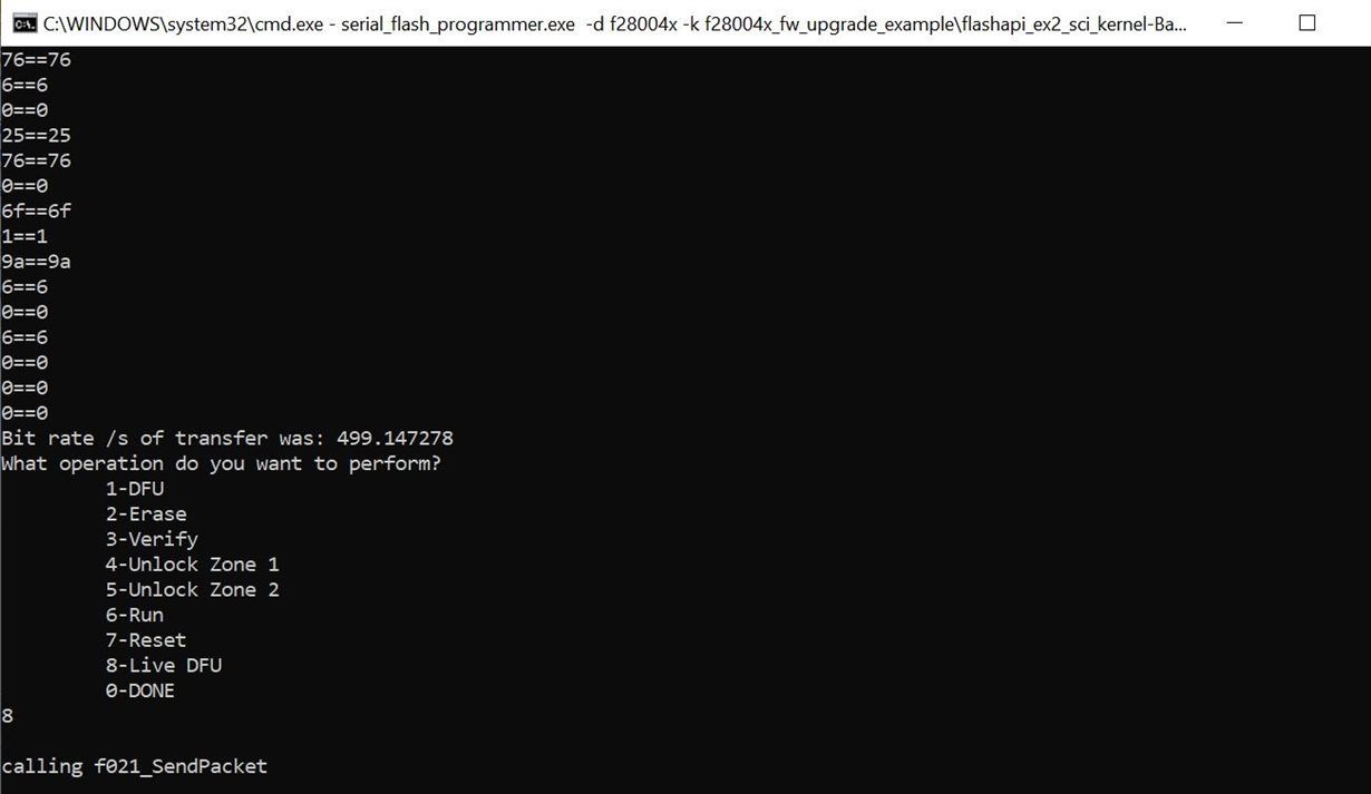
And this is what Mine looks like:

I have tried waiting but nothing ever pops up after this. How can I get the prompt I need to run the DFU?

Thank you for your help,

Trevor

  • Trevor,

    Can you send me the exact command that you sent in this case?

    Also what hardware are you using?

    Thanks,

    Sira

  • I am using the TMS320F28377S Microcontroller with custom hardware. I have verified that the serial communication works properly from previous programs that I flashed using the jtag connector and the screenshot that I posted of my system shows that it does properly send and receive the data.

    I threw the necessary files into the same folder to make it easier for me. The command I am using is this:

    serial_flash_programmer.exe -d f2837xS -k F2837xS_sci_flash_kernel.txt -a my_program.txt -p COM5 -b 9600 -w -v

    I also tried without the -w -v and it finished after the line about the Bit rate. I also tried with -q -w -v and it did not show the compared hex numbers.

    Thank you for your help,

    Trevor

    edit: if you are asking about my computer with regards to hardware, I am running windows 10 on a nice computer that is about a year old

  • Please check the following issue link to see if there might be a connection here (custom hardware)

    https://e2e.ti.com/support/microcontrollers/c2000/f/171/p/895434/3317073#3317073

    Since this is a single C28x core device, you should expect to see slightly different options, as in the picture below. Then the option to select would be "1 DFU".

    I can try this at my end, but I don't have a F2837xs controlCARD. I do have a F2837xd controlCARD. I can give it a shot with that, but I won't be able to use the single core .txt file. I can ask a colleague to help as well.

  • Unfortunately I am not offered a menu of options at all as shown in the screenshot in my original question. The last thing the command prompt says is Attempting autobaud to send function message...

    After I get this message I am not allowed to input anything at all. There is no menu of options. it looks like it is stuck in an infinite while loop trying to do something with autobaud and it is not working.

    is there a way to fix this issue? any help would be appreciated.

  • Trevor,

    Yes, I understand that. Just pointing out that when your issue does get resolved, you will see a different command window than what your initial message indicated.

    In your case, it looks like f021_DownloadKernel() function on the host side is executing properly. This function includes an Autobaudlock(), followed by loading the Kernel program to CPU1 RAM. Once this function returns, it once again attempts to Autobaud lock. This is where it is hanging.

    On the target side, once the Kernel is in CPU1 RAM, it does required initialization and then tries to Autobaud lock with the host.

    I'll continue looking into this.

    Thanks,

    Sira

  • Trevor,

    Can you verify that the kernel you are using is built with the correct SCI GPIOs configured?

    Thanks,

    Sira

  • Hi Sira,

     I have the much similar issue like this thread. pls refer my thread:

    I use the default SCI kernel under c:\ti\controlSUITE\device_support\~Utilities\serial_flash_programmer\F2837xD_sci_flash_kernels_cpu01,

    and it works when branch SCI boot by GPIO72 with Low and GPIO84 with High. so, it should not be the SCI GPIO problem, right?

    and in my flash application, GPIO84 and 85 are used for SCI boot.

    Looking forward to your reply.

    Feng

  • Feng,

    Good that you have confirmed this. I was just trying to make sure the same is true in Trevor's case as well, since he is using custom HW and the F2837xs. So I believe there has to be an SCI Boot mode that is correctly set, and then the right SCI pins configured to send the image to the device.

    Thanks,

    Sira

  • Hi, Sira,

    So can you please help on my problem described in my  thread? Or give me some advice how to debug it.

    Feng

  • Feng,

    I'll give it a shot. Anyway Chris (who is helping you) and I are on the same team, and synced up on this.

    Thanks,

    Sira

  • Yes, I know Chris is helping me. And I am waiting for his reply.

    Since it is urgent for me, so at the same time I seek other's help, such as you.

    Anyway, thanks both of you. And looking forward to your reply.

    Feng

  • Hi Sira,

    SCITXDC is GPIO72 and SCITXDA is GPIO84. I don't think this should be an issue because when JMP102 is connected it goes into the boot mode and when it is not it runs normally.

    GPIO84 and 85 are used for transmitting and receiving data just as Feng has his. 

    is there something else I need to do to make sure the SCI Boot mode is correctly set?

    is there something in the kernel that I need to check? I am running the default kernel found here: ti\c2000\C2000Ware_1_00_06_00\device_support\f2837xs\examples\cpu1\F2837xS_sci_flash_kernel

    Thank you for all of the help

    Trevor

  • Trevor,

    Just to rule out any issues with old code, can you try the kernel in the newest version of C2000Ware?

    C2000Ware_3_01_00_00\device_support\f2837xs\examples\cpu1\F2837xS_sci_flash_kernel

    Thanks,

    Sira

  • Sira,

    that was a good thought but unfortunately that did not fix the issue.

    Thanks,

    Trevor

  • Trevor,

    Since this thread has gotten quite long, a summary of where we stand:

    1. You're using the F2837xS, Feng's is F28379D. (he mistakenly used F28379S in the thread title and tag, I edited it)

    2. Feng is able to get the SCI Boot mode to work properly - download the Kernel and then use DFU to download the Application. He runs into an issue when he uses Flash boot, and then within main(), he calls SCI_Boot(). Your case is different, you're running into an issue with SCI Boot mode itself.

    3. Even within SCI Boot mode, Feng runs into an issue when he uses the CCS project to build the Kernel.txt. If he uses the default Kernel.txt, it works. These are from ControlSUITE. I've asked him to try a similar approach with C2000Ware. This is not applicable in your case because you're using F2837xS, where we only have the project and no default .txt file. So we need to build the project. I use CCSv9.3 and TI Compiler v18.12.4.LTS.

    4. Do you have Visual Studio installed? The next step would be to try and debug the issue using VS. You could also try removing the Autobaud lock feature from the serial flash programmer solution as well as the target side configuration. For your convenience, I am attaching the corresponding VS executable with autobaud lock removed. This has autobaud lock removed from serial_flash_programmer.cpp main() within the condition block else if (g_bf021 == true && (g_bf2807x || g_bf2837xS || g_bf28004x)) after returning from f021_DownloadKernel(). Note that the autobaud lock call within f021_DownloadKernel() still exists as that would autobaud lock with the SCI ROM bootloader. On the target side, you would need to remove the autobaud lock call SCIA_AutobaudLock() inside SCI_GetFunction() in SCI_GetFunction.c.

    https://e2e.ti.com/cfs-file/__key/communityserver-discussions-components-files/171/serial_5F00_flash_5F00_programmer_5F00_no_5F00_autobaudlock.exe

    Can I ask what your broader plans are? Do you plan on using SCI boot to upgrade firmware, and Flash boot otherwise? I don't suppose you plan on having a custom Bootloader resident in Flash.

    Thanks,

    Sira

  • Hi Sira,

    3. Even within SCI Boot mode, Feng runs into an issue when he uses the CCS project to build the Kernel.txt. If he uses the default Kernel.txt, it works. These are from ControlSUITE. I've asked him to try a similar approach with C2000Ware. This is not applicable in your case because you're using F2837xS, where we only have the project and no default .txt file. So we need to build the project. I use CCSv9.3 and TI Compiler v18.12.4.LTS.

    I built the project using CCS 8.0.0 and TI Compiler ti-cgt-c2000_18.1.1.LTS to generate the .out file and then in the command line I generated the .txt file with these commands:

    hex2000.exe -boot -a -sci8 blinky_cpu01.out -o blinky_cpu01.txt
    hex2000.exe -boot -a -sci8 F2837xS_sci_flash_kernel.out -o F2837xS_sci_flash_kernel.txt

    4. Do you have Visual Studio installed? The next step would be to try and debug the issue using VS. You could also try removing the Autobaud lock feature from the serial flash programmer solution as well as the target side configuration. For your convenience, I am attaching the corresponding VS executable with autobaud lock removed. This has autobaud lock removed from serial_flash_programmer.cpp main() within the condition block else if (g_bf021 == true && (g_bf2807x || g_bf2837xS || g_bf28004x)) after returning from f021_DownloadKernel(). Note that the autobaud lock call within f021_DownloadKernel() still exists as that would autobaud lock with the SCI ROM bootloader. On the target side, you would need to remove the autobaud lock call SCIA_AutobaudLock() inside SCI_GetFunction() in SCI_GetFunction.c.

    I am working to get Visual Studio installed now. in the meantime I replaced the serial flash programmer with the one you attached and modified the kernel and replaced it. I then ran the serial flash programmer and got stopped at the same spot where it says attempting autobaud to send function message.

    Can I ask what your broader plans are? Do you plan on using SCI boot to upgrade firmware, and Flash boot otherwise? I don't suppose you plan on having a custom Bootloader resident in Flash.

    We will not have access to the Jtag connector during the production of this product so we need to flash a fresh micro in a different way. eventually we will switch to flashing with CAN but were told we need to modify the SCI code to work with CAN so I am starting by trying to flash a micro with SCI.

    Thanks,

    Trevor

  • Thanks Trevor.

    I also replied to your post on Feng's thread. Not sure if you saw it.

    Pasting a relevant portion below - would be worth a try. I believe you are using GPIO 84, 85, so it should be SCI_BOOT in your case.

    -------

    An interesting clue from there as well. It points to this line of code in F2837xS_sci_flash_kernel.c

    //
    // parameter SCI_BOOT for GPIO84,85; parameter SCI_BOOT_ALTERNATE for
    // GPIO28,29
    //
    EntryAddr = SCI_GetFunction(SCI_BOOT_ALTERNATE);

    Something to switch and try.

    -------

    Thanks,

    Sira

  • Sira,

    thank you again for your help.

    Now that I can run the DFU I need to figure out how to run the software that I am trying to flash. do I need to run the program once before cycling power and putting GPIO72 back high? 

    I am running into the issue where if I flash from the Jtag connector I can then run the program and cycle power and it will run again but if I try to flash through the serial programmer the code does not run. 

    Thanks,

    Trevor

  • Trevor,

    I know exactly what you mean. I think I ran into a similar issue just recently, although I am unable to put a finger on how I resolved it.

    So the expected behavior would be that the Kernel is downloaded to RAM, and it facilitates the transfer and programming of the Application image to Flash. When the process is complete, before you cycle power, can you connect to the target through JTAG and view the Flash memory contents in CCS? See if it is correctly getting programmed.

    And of course before you power cycle, you will switch to Flash boot (which I believe is what pulling GPIO72 high accomplishes).

    Thanks,

    Sira

  • Sira,

    to clarify further:

    on this development board I am either flashing with Jtag or the serial flash programmer and I do not need to use CCS to see if the program is working properly (I have some LEDs and other stuff to see if it is working). 

    When I flash with Jtag it the program works properly but when I run DFU with the serial flash programmer it does not work as I expect.

    But on the final product I will never have access to Jtag so I will need to use the serial flash programmer to flash the micro.

    thanks,

    Trevor

  • Trevor,

    I understand.

    I still recommend using CCS (after DFU using SCI Boot, but before cycling power) per my previous reply to you, to understand what's going on. Is nothing getting programmed to Flash? Is it getting partially programmed?

    Thanks,

    Sira

  • Trevor,

    I thought about this, and my analysis was along these lines:

    • maybe device isn’t getting properly initialized inside the kernel
    • so it isn’t set up to write to flash correctly even though it indicates it is doing so

    So I went and compared main() of F2837xS_sci_flash_kernel and F2837xD_sci_flash_kernels_cpu01 projects. I notice the following key difference:

    - the F2837xD project calls a function InIt_Flash_Sectors() defined in the same source file, that initializes the Flash API and flash sectors.

    - the F2837xS project does not.

    Can you try doing this and checking? I'd suggest copying over the same function.

    Thanks,

    Sira

  • Let me know if you were able to give this a shot.

    Thanks,

    Sira

  • Sorry I was pulled away from this but I should be able to test it within the next few days.
  • Sounds good. I'll change the status on the thread to "Waiting for Customer", and we'll pick it up when you're ready.

    Thanks,

    Sira

  • Hi Sira,

    I was able to get back to this and I tried copying the Init_Flash_Sectors function into the F2837xS_sci_flash_kernel but it gave me an error:

    #20 identifier "F021_CPU0_BASE_ADDRESS" is undefined

    This error did not pop up in the F2837xD project so I tried searching the F2837xD project for "F021_CPU0_BASE_ADDRESS" and I only found it in the Init_Flash_Sectors function and nowhere else. 

    I assume this is defined somewhere in one of the include files and it seems like a necessary part of the function so I will continue to search for it but please let me know if you have any more information on what it is or how to fix this.

    Thanks,

    Trevor

  • Trevor,

    You'll find them in Constants.h here respectively.

    C:\ti\c2000\C2000Ware_3_01_00_00\libraries\flash_api\f2837xs\include\Constants

    C:\ti\c2000\C2000Ware_3_01_00_00\libraries\flash_api\f2837xd\include\Constants

    To fix the error, please replace F021_CPU0_BASE_ADDRESS with F021_CPU0_W0_BASE_ADDRESS. This needs to be done because _F2837xS is always defined in F021_F2837xS_C28x.h.

    Thanks,

    Sira

  • Sira,

    I tried this and it no longer has an error when building but it still did not fix the issue.

    I was going back through your comments and you said I should view the Flash memory contents in CCS. I was not aware that I can do that without flashing from CCS. I found this https://e2e.ti.com/support/microcontrollers/c2000/f/171/t/573119.

    From what I can tell there should be 2 ways to access the memory window: Select View->Memory. OR Click the View Memory button on the Debug toolbar.But in View there is memory browser and memory allocation. From what I can tell it looks like neither of these are what I am looking for and the view memory button does not seem to exist on my system. How can I view the flash memory contents in CCS version 8?

    Thanks,

    Trevor

  • Trevor,

    View -> Memory browser is what I use. You can enter the memory address as 0x98000 and it will show values in the browser beginning at that address.

    Just launch the appropriate target configuration file (i.e. for the F2837xS Launchpad - XDS100v2 Debug probe).

    Thanks,

    Sira

  • Sira,

    The code starts writing at the correct address and writes just under A00 (hex) addresses before switching to FFFF for a massive chunk of memory addresses. It will then switch back and forth between large chunks of memory addresses being FFFF and small chunks of memory addresses being written. based on the CMD file, the flash is currently structured into one large continuous block. Should I break this up into smaller blocks to work with the serial flash programmer?

    Thanks,

    Trevor

  • Trevor,

    Very strange. I've asked a Flash expert for advice.

    Remind me - is this still on the F2837xS launchpad, or is it on your custom HW?

    Thanks,

    Sira

  • Sira,

    This is on my own custom HW. I was not able to flash the launchpad before you solved my earlier issue.

    Thanks,

    Trevor

  • Trevor,

    Sure, give that a shot. Can you send me your linker cmd file?

    Also, can you check if the Flash ECC corresponding to the locations you are writing to are programmed or not? You can check the F2837xS datasheet SPRS881H Flash Memory map for ECC addresses.

    Thanks,

    Sira

  • Sira,

    Sure, give that a shot. Can you send me your linker cmd file?

    see attached. Is there something in particular that you are looking for in this file?

    Also, can you check if the Flash ECC corresponding to the locations you are writing to are programmed or not? You can check the F2837xS datasheet SPRS881H Flash Memory map for ECC addresses.

    I am going to try to answer this as best as I can with the limited understanding that I have. the Flash ECC locations are from 0x0107 0000 to 0x0107 007F. the data in these locations are the same if I flash through the Jtag connector or if I flash through the Serial Flash Programmer. Since the program works fine if flashed through Jtag I assume this is fine.

    Thanks,

    Trevor

    it is not letting me attach a CMD file so I put the code into a .txt file

    MEMORY
    {
    PAGE 0 :  /* Program Memory */
              /* Memory (RAM/FLASH) blocks can be moved to PAGE1 for data allocation */
              /* BEGIN is used for the "boot to Flash" bootloader mode   */
    
       RAMM0           		: origin = 0x000122, length = 0x0002DE
       /* D0, D1 RAM combined	*/
       RAM_D0_D1       		: origin = 0x00B000, length = 0x001000
       /* L0, L1, L2, L3 RAM combined: DCSM secure, CLA Program RAM */
       RAM_LS0_LS1_LS2_LS3	: origin = 0x008000, length = 0x002000
       RESET           		: origin = 0x3FFFC0, length = 0x000002
       
       /* Flash sectors */
       BEGIN           		: origin = 0x080000, length = 0x000002
       FLASHA           	: origin = 0x080002, length = 0x001FFE	/* on-chip Flash */
    
       /* FLASH Sectors B,C,D,E,F,G,H,I,J,K,L,M,N combined - DCSM secure */
       FLASH_COMBINED	: origin = 0x082000, length = 0x03E000
       //FLASH_COMBINED	: origin = 0x080002, length = 0x03FFFE
    
    PAGE 1 : /* Data Memory */
    
    	BOOT_RSVD       : origin = 0x000002, length = 0x000120     /* Part of M0, BOOT rom will use this for stack */
    	RAMM1           : origin = 0x000400, length = 0x000400     /* on-chip RAM block M1 */
    
    	CLA1_MSGRAMLOW	: origin = 0x001480, length = 0x000080     /* CLA to CPU Message RAM, DCSM secure */
    	CLA1_MSGRAMHIGH	: origin = 0x001500, length = 0x000080     /* CPU to CLA Message RAM, DCSM secure */
    
    	RAMLS4		: origin = 0x00A000, length = 0x000800	/* L4 RAM, DCSM secure, CLA Data RAM */
    	RAMLS5	   	: origin = 0x00A800, length = 0x000800	/* L5 RAM, DCSM secure, CLA Data RAM */
    
    	RAMGS0      : origin = 0x00C000, length = 0x001000
    	RAMGS1      : origin = 0x00D000, length = 0x001000
    	RAMGS2      : origin = 0x00E000, length = 0x001000
    	RAMGS3      : origin = 0x00F000, length = 0x001000
    	RAMGS4      : origin = 0x010000, length = 0x001000
    	RAMGS5      : origin = 0x011000, length = 0x001000
    	RAMGS6      : origin = 0x012000, length = 0x001000
    	RAMGS7      : origin = 0x013000, length = 0x001000
    	RAMGS8      : origin = 0x014000, length = 0x001000
    	RAMGS9      : origin = 0x015000, length = 0x001000
    	RAMGS10     : origin = 0x016000, length = 0x001000
    	RAMGS11		: origin = 0x017000, length = 0x000FFE
    }
    
    SECTIONS
    {
    
    	  /* Program memory (PAGE 0) sections */
    	.text               : > FLASH_COMBINED,   PAGE = 0
    	.cinit              : > FLASH_COMBINED,   PAGE = 0
    	.const              : > FLASH_COMBINED,   PAGE = 0
    	.econst             : > FLASH_COMBINED,   PAGE = 0
    	.pinit              : > FLASH_COMBINED,   PAGE = 0
    	.reset              : > RESET,            PAGE = 0, TYPE = DSECT  /* Not using the .reset section */
    	.switch             : > FLASH_COMBINED,   PAGE = 0
    
    						 
       /* Allocate uninitalized data sections: */
       .bss                : >> RAMGS0 | RAMGS1		PAGE = 1
       .ebss               : >> RAMGS0 | RAMGS1		PAGE = 1
       .cio                : > RAMM1,               PAGE = 1
       .stack              : > RAMM1,               PAGE = 1
       .sysmem             : > RAMM1,               PAGE = 1
       .esysmem            : > RAMM1,               PAGE = 1
    
       /*** User Defined Sections ***/
    	codestart           : > BEGIN       PAGE = 0, ALIGN(4)
    	ramfuncs            : LOAD = FLASH_COMBINED,
    						  //RUN = RAMLS0 | RAMLS1,
    						  RUN = RAM_D0_D1,
                              LOAD_START(_RamfuncsLoadStart),
                              LOAD_SIZE(_RamfuncsLoadSize),
                              LOAD_END(_RamfuncsLoadEnd),
                              RUN_START(_RamfuncsRunStart),
                              RUN_SIZE(_RamfuncsRunSize),
                              RUN_END(_RamfuncsRunEnd),
                              PAGE = 0, ALIGN(4)
    
    	ControlRam          : >> RAMGS0 | RAMGS1,		PAGE = 1
    	.scratchpad         : >> RAMLS4 | RAMLS5,		PAGE = 1	/* Scratchpad memory for the CLA C Compiler */
    	Cla1ToCpuMsgRAM		: >  CLA1_MSGRAMLOW,		PAGE = 1	/* Link to CLA Message RAM */
    	CpuToCla1MsgRAM     : >  CLA1_MSGRAMHIGH,		PAGE = 1	/* Link to CLA Message RAM */
    	Cla1Data1           : >> RAMLS4 | RAMLS5,		PAGE = 1	/* Link to CLA Data RAM */
    
    							/* Load to flash, run from CLA Program RAM */
    	Cla1Prog			:	LOAD = FLASH_COMBINED, PAGE = 0
                              	RUN_START(_Cla1Prog_Start)
                              	RUN = RAM_LS0_LS1_LS2_LS3,	PAGE = 0
                              	LOAD_START(_cla1Funcs_loadstart),
                              	LOAD_SIZE(_cla1Funcs_loadsize),
                              	RUN_START(_cla1Funcs_runstart)
    
    	ControlProg			:	LOAD = FLASH_COMBINED, PAGE = 0
    	                        RUN = RAM_D0_D1, PAGE = 0
                              	LOAD_START(_ControlProg_loadstart),
                              	LOAD_SIZE(_ControlProg_loadsize),
                              	LOAD_END(_ControlProg_loadend),
                              	RUN_START(_ControlProg_runstart)
                              	RUN_SIZE(_ControlProg_runsize),
                              	RUN_END(_ControlProg_runend)
    }
    
    /*
    //===========================================================================
    // End of file.
    //===========================================================================
    */
    

  • Trevor,

    You looked at TI-OTP ECC address space.  Please see the next page (page 180 in datasheet) for Flash ECC range and confirm whether the ECC is programmed correctly or not.

    Could you attach your application map file as well?

    Thanks and regards,
    Vamsi

  • Trevor,

    As Vamsi mentions, you missed the next page Pg 180 which contains the continuation of Table 6-2 and the per sector Flash ECC. That's what Vamsi wanted you to check.

    Thanks,

    Sira

  • Vamsi and Sira,

    I took out a few sensitive lines from the map file but it is for the most part entirely there.

    after checking the flash ECC locations I noticed a few things:

    in the data sheet sector 0 starts at 0x0108 0000 and the sectors count up in memory until sector 14 where it starts back at 0x0108 0000. Is there a reason for this?

    I am indeed missing large amounts of data from the Flash ECC sectors that I was not missing when I flashed from JTAG. 

    the data did not cut out at the beginning or end of flash sectors. it cut out randomly in the middle somewhere and came back on in seemingly random locations. I say random but when I flash data it looks like it cuts out and turns back on in the same locations each time I run the serial flash programmer. 

    the data that is there is the same as what is stored when I flash with JTAG other than the one location that is used in sector 0.Map File.txt

    Thanks,

    Trevor

  • Trevor,

    That ECC space address for second bank is incorrect in the datasheet.  I will file a ticket and notify our documentation team to fix that.  Thank you.

    We will review your memory map and get back to you.

    Thanks and regards,

    Vamsi

  • Trevor,

    1) Hope you are using the latest Flash kernels from C2000Ware_3_01_00_00.

    2) In your linker cmd file, please align all the sections mapped to Flash on 128-bit boundary. See the usage of ALIGN(8) in the linker cmd file at C2000Ware_3_01_00_00\device_support\f2837xs\common\cmd\2837xS_Generic_FLASH_lnk.cmd.

    Above is very important when using kernels to load your application. See if this helps any.

    3) Another minor thing in linker cmd: Please update the origin and length of RAMM0 as below:

    RAMM0            : origin = 0x000123, length = 0x0002DD

    Thanks and regards,

    Vamsi 


  • Vamsi and Sira,

    2) In your linker cmd file, please align all the sections mapped to Flash on 128-bit boundary. See the usage of ALIGN(8) in the linker cmd file at C2000Ware_3_01_00_00\device_support\f2837xs\common\cmd\2837xS_Generic_FLASH_lnk.cmd.

    Above is very important when using kernels to load your application. See if this helps any.

    This did resolve my issue but I am just curious, why does this matter when using the serial flash programmer but not when using Jtag? the program worked just fine without this modification when I was flashing with Jtag


    Thank you both for the help! it is really appreciated. 

    Trevor

  • Trevor,

    Great to hear! I'll let Vamsi comment on your question.

    I'd like you to test one thing - remember we earlier added InitFlashSectors() in main(). What happens if you remove that? Does it still work or result in errors? This will let me know whether or not to file a bug and make changes to the F2837xS kernel.

    Thanks,

    Sira

  • Trevor,

    Glad it helped.

    Flash wrapper logic in the device can program a max of 128-bits at-a-time when the address is 128-bit aligned.  

    When I developed TI Flash tools (CCS Flash Plugin and UniFlash), I assumed that users may not align the sections on 128-bit boundary and designed them to handle that case as well.  Flash kernels does not handle this case.  Hence, I suggest users to align the start address of the sections on the 128-bit boundary.  This way, Flash kernels when it calls Flash API, will pass 128-bit address.

    Hope this helps.

    Thanks and regards,

    Vamsi


  • Sira,

    it did work properly without the additional function so no ticket required there but in the datasheet table 6-14 it for SCI-Boot0 in the notes section it says 'default SCI option when chosen through Boot Mode GPIOs' 

    This should be moved to SCI-Boot1 because by default the kernel uses GPIO28 and 29 and you noticed that I needed to change that.

    thank you both again for your help,

    Trevor

  • Trevor,

    Thanks for the feedback.

    Sira