This thread has been locked.

If you have a related question, please click the "Ask a related question" button in the top right corner. The newly created question will be automatically linked to this question.

TMS320F28069M: PMSM starts with Hall sensor and then switching to FOC control

Part Number: TMS320F28069M
Other Parts Discussed in Thread: MOTORWARE

I have a 28069()M based customized board, which is used to control PMSM equipped with an incremental encoder (2500 pulses/rev) as well as Hall sensor on it. The servo position control/speed control/torque control are required to be implemented on it.  With reference to TI motorware example project Lab11 ~ lab12x; I have realized the above function with this encoder without sensorless control.

Currently, before motor starting, there is a rotor alignment process then the motor will move normally according to command received. I do not expect that happens since there are Hall sensor signals available in the encoder. May be we can start with Hall sensor signal directly without any rotor alignment process. I do not want to use absolute encoders here.

In the example Project Lab11 ~12x, there is an example source code that the motor will start based on Hall signal then when motor speed is up to some threshold , the control will switch from Hall based control to FOC control based on the 2500 lines encoder. this is good. But this speed threshold may be hundreds RPM, this is too high for my application. As you know, in some cases, the servo motor may start with a very low speed in position control mode, therefore, the above speed threshold setting method in example projects may not be feasible to my servo requirements. 

Therefore, I am thinking that whether there is a possibility that the motor start with Hall sensor, when one electric cycle  including six Hall sections (or less) are completed, the motor will switch smoothly from trapezoidal control mode to FOC control mode, in this case, the transition will not depend on the setting speed threshold, but depend on the Hall signal sections. By doing this, the motor may start definitely based on bldc mode (Hall sensor signal based) but switching to FOC mode (incremental encoder based) as fast as possible, for example, may be within one electric cycle or less time, the motor will switch to FOC mode. 

Does any one have the similar development experiences like that? Any suggestions or even source code example are very appreciated.

Thank you.

  • Yes, you just need to use the U/V/W hall sensor to achieve an initial position of the rotor for a startup without force alignment and don't need to implement the trapezoidal control as well. Unfortunately, there is no such example code based on C2000 in motorWare for your reference, you might have to design the code by yourself.

    Or you might refer to the following link about a very old reference code for BLDC.

    [FAQ] Trapezoidal Control of BLDC Motors Using Hall Effect Sensors on C2000 Controller

  • Hi Yanming,

    Thanks for your comments. I will review the content you mentioned in the link.

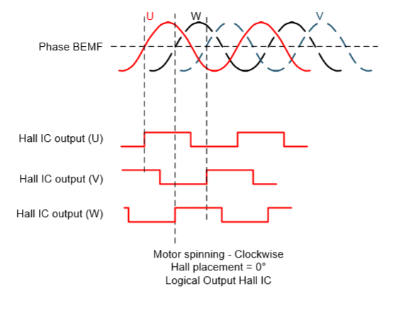
    I have tried to implement what I described in the post, The motor can start up using Hall sensor signal U/V/W with trapezoidal control mode successfully, but when switching to FOC mode, it fails. The main reason is that the rotor position angle is not known correctly during the transitions.  Therefore, the question is becoming how do we know the exact rotor position angle based on Hall U/V/W signals, especially the angle while transiting to FOC control. 

    What is the true relationship between Hall U/V/W signal and rotor angle? I have surveyed some materials, but it looks different with different speakers, so I now is confused. 

    This figure is from one of TI application report: " Adaptive drive angle adjust" , which shows the phase relationship between motor back EMP and Hall sensor signals. From this figure, we can conclude that the up-rising of Hall sensor U is aligned with the absolte 0 electric degree of back EMF U, which actually is also  absolute zero angle used in FOC control. Therefore, in terms of Hall sensor U/V/W, we may draw the rough angle values of rotor angle. But How ? from this figure, for 120 degree conduction mode, it is not possible to realize. for example, if we want to conduct phase U in positive half cycle for 120 degree, then at the moment of 30 degree after up-rising edge of Hall U, the phase U Upper switch should be on; but there is no U/V/W  signal changment at that moment until 60 degree. Is there any mistake on the figure?

    Another question, if it is correct in the figure, then I can get instantaneous rotor angle value while Hall U/V/W signals changment happens. Then I can switch to FOC control at that moment, right?

    . Any explanation or suggestion appreciated, thank you.

  • You might refer to the lab11e in MotorWare which can be downloaded as the link below.

    http://www.ti.com/tool/motorware

    And you may have a look at the links below about lab11e.

    https://e2e.ti.com/support/microcontrollers/c2000/f/171/p/883444/3294852

    https://e2e.ti.com/support/microcontrollers/c2000/f/171/t/670979

  • Hi,

    I have the same question.

    When the Hall U transitions positive (aligned to be at the same time BEMF U-V goes positive),  I would like to set the FOC angle.

    Given d-axis initial alignment for electrical zero, what is the correct electrical angle when BEMF U-V goes positive?

    If at this transition the FOC angle is set to zero, the motor bumps slightly indicating the new angle is not correct.

    Were you able to answer this question?

    Thanks. 

  • You might have a look at the lab guide and the example code for lab11e in motorWare that could have an answer to your question.

    MotorWare:  http://www.ti.com/tool/motorware

    \ti\motorware\motorware_1_01_00_18\docs\labs