Hello
I have a problem that is related to EPWM output from TMS320F28377S.
Two control boards are synchronized to control the circuit.
The master board performs control and sends a duty reference to the slave board using SPI communication.
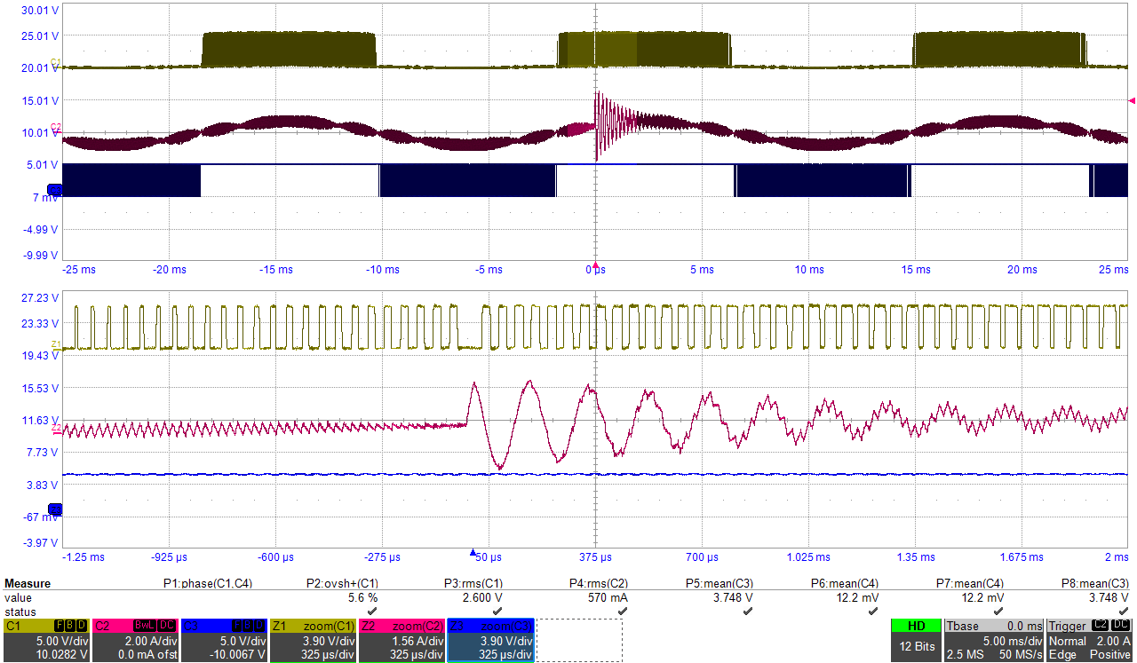
However, PWM does not occur at one cycle during the PWM operation as shown in the picture.
The PWM port where the above phenomenon occurs has no regularity, and the constant occurs only in the duty section of about 0.5.
ADC interrupt and SPI interrupts are working in Slave Board.
At first, two interrupts were operated, so it was expected that they would collide with each other.
If the power conversion circuit does not operate, it operates normally. So I think the interrupt seems to be fine. and the initialization code seems to be fine too.
I really appreciate it if you could give me any hint or suggestions.
Thank you very much.