- Ask a related questionWhat is a related question?A related question is a question created from another question. When the related question is created, it will be automatically linked to the original question.

Tool/software: Code Composer Studio
Hello,
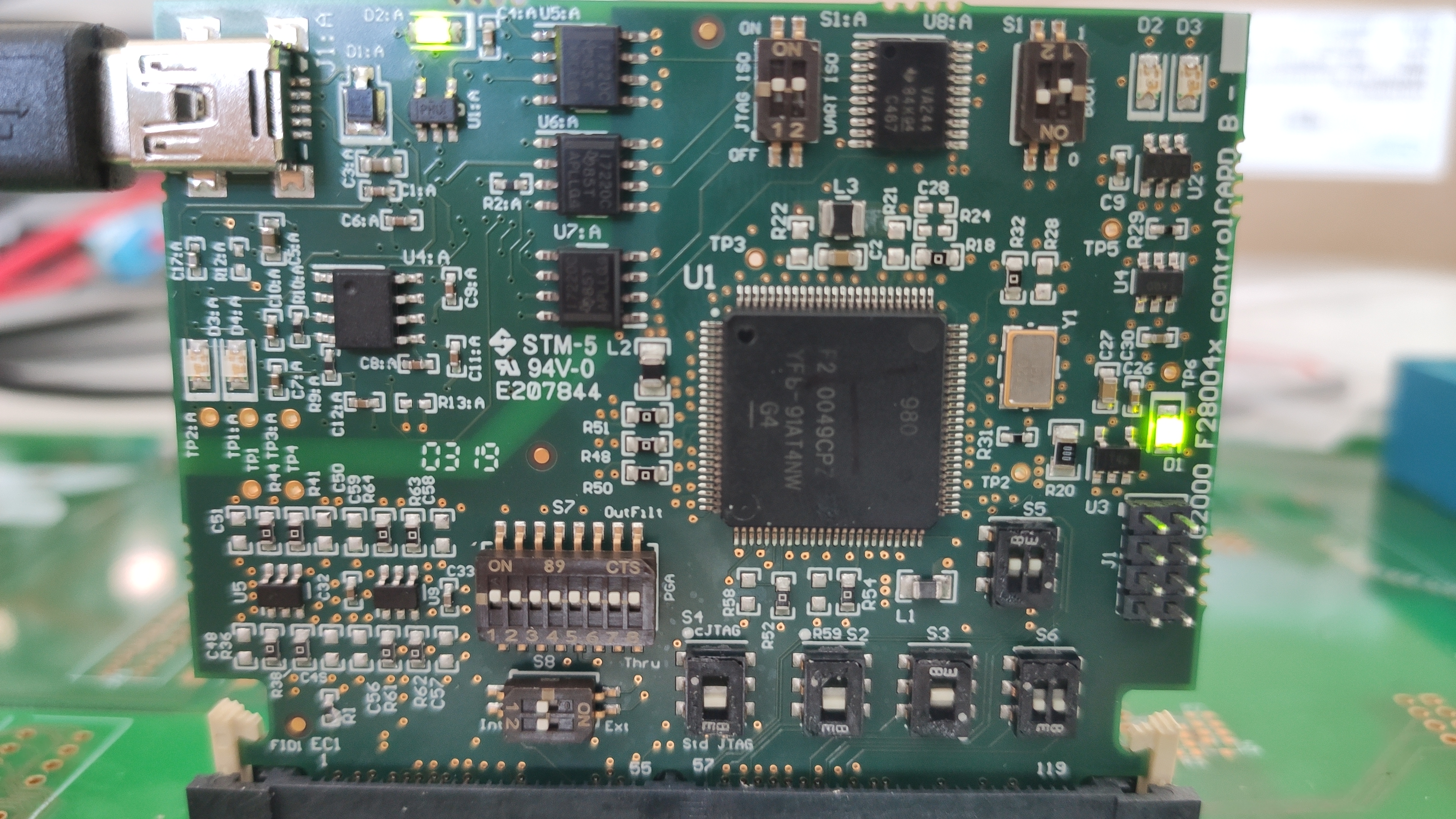
i would like to connect the controlcard F280049C to my computer but the connection test fails. I added the log to this article.
The controlboard is connected to a self designed mainboard with the following configuration.
HSEC8 - 120 Connection:
Switch configuration:
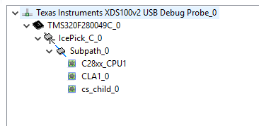
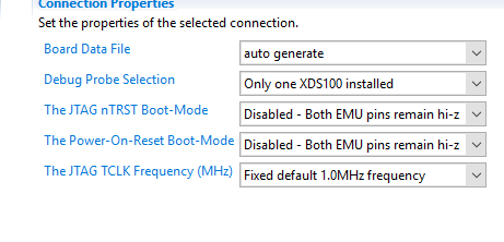
Software Konfiguration
LOG
[Start: Texas Instruments XDS100v2 USB Debug Probe_0]
Execute the command:
%ccs_base%/common/uscif/dbgjtag -f %boarddatafile% -rv -o -F inform,logfile=yes -S pathlength -S integrity
[Result]
-----[Print the board config pathname(s)]------------------------------------
C:\Users\MASTER~1\AppData\Local\TEXASI~1\
CCS\ccs1010\0\0\BrdDat\testBoard.dat
-----[Print the reset-command software log-file]-----------------------------
This utility has selected a 100- or 510-class product.
This utility will load the adapter 'jioserdesusb.dll'.
The library build date was 'May 7 2020'.
The library build time was '21:10:18'.
The library package version is '9.2.0.00002'.
The library component version is '35.35.0.0'.
The controller does not use a programmable FPGA.
The controller has a version number of '4' (0x00000004).
The controller has an insertion length of '0' (0x00000000).
This utility will attempt to reset the controller.
This utility has successfully reset the controller.
-----[Print the reset-command hardware log-file]-----------------------------
The scan-path will be reset by toggling the JTAG TRST signal.
The controller is the FTDI FT2232 with USB interface.
The link from controller to target is direct (without cable).
The software is configured for FTDI FT2232 features.
The controller cannot monitor the value on the EMU[0] pin.
The controller cannot monitor the value on the EMU[1] pin.
The controller cannot control the timing on output pins.
The controller cannot control the timing on input pins.
The scan-path link-delay has been set to exactly '0' (0x0000).
-----[The log-file for the JTAG TCLK output generated from the PLL]----------
There is no hardware for programming the JTAG TCLK frequency.
-----[Measure the source and frequency of the final JTAG TCLKR input]--------
There is no hardware for measuring the JTAG TCLK frequency.
-----[Perform the standard path-length test on the JTAG IR and DR]-----------
This path-length test uses blocks of 64 32-bit words.
The test for the JTAG IR instruction path-length failed.
The many-ones then many-zeros tested length was 6 bits.
The many-zeros then many-ones tested length was -2016 bits.
The test for the JTAG DR bypass path-length failed.
The many-ones then many-zeros tested length was 32 bits.
The many-zeros then many-ones tested length was -2016 bits.
-----[Perform the Integrity scan-test on the JTAG IR]------------------------
This test will use blocks of 64 32-bit words.
This test will be applied just once.
Do a test using 0xFFFFFFFF.
Test 1 Word 0: scanned out 0xFFFFFFFF and scanned in 0xFFFFFFC1.
Scan tests: 1, skipped: 0, failed: 1
Do a test using 0x00000000.
Test 2 Word 0: scanned out 0x00000000 and scanned in 0x0000003F.
Scan tests: 2, skipped: 0, failed: 2
Do a test using 0xFE03E0E2.
Test 3 Word 0: scanned out 0xFE03E0E2 and scanned in 0x80F83881.
Test 3 Word 1: scanned out 0xFE03E0E2 and scanned in 0x80F838BF.
Test 3 Word 2: scanned out 0xFE03E0E2 and scanned in 0x80F838BF.
Test 3 Word 3: scanned out 0xFE03E0E2 and scanned in 0x80F838BF.
Test 3 Word 4: scanned out 0xFE03E0E2 and scanned in 0x80F838BF.
Test 3 Word 5: scanned out 0xFE03E0E2 and scanned in 0x80F838BF.
The details of the first 8 errors have been provided.
The utility will now report only the count of failed tests.
Scan tests: 3, skipped: 0, failed: 3
Do a test using 0x01FC1F1D.
Scan tests: 4, skipped: 0, failed: 4
Do a test using 0x5533CCAA.
Scan tests: 5, skipped: 0, failed: 5
Do a test using 0xAACC3355.
Scan tests: 6, skipped: 0, failed: 6
Some of the values were corrupted - 67.2 percent.
The JTAG IR Integrity scan-test has failed.
-----[Perform the Integrity scan-test on the JTAG DR]------------------------
This test will use blocks of 64 32-bit words.
This test will be applied just once.
Do a test using 0xFFFFFFFF.
Test 1 Word 0: scanned out 0xFFFFFFFF and scanned in 0x0BB1A02F.
Scan tests: 1, skipped: 0, failed: 1
Do a test using 0x00000000.
Test 2 Word 0: scanned out 0x00000000 and scanned in 0xFFFFFFFF.
Scan tests: 2, skipped: 0, failed: 2
Do a test using 0xFE03E0E2.
Test 3 Word 0: scanned out 0xFE03E0E2 and scanned in 0x00000001.
Scan tests: 3, skipped: 0, failed: 3
Do a test using 0x01FC1F1D.
Test 4 Word 0: scanned out 0x01FC1F1D and scanned in 0xFE03E0E3.
Scan tests: 4, skipped: 0, failed: 4
Do a test using 0x5533CCAA.
Test 5 Word 0: scanned out 0x5533CCAA and scanned in 0x01FC1F1D.
Scan tests: 5, skipped: 0, failed: 5
Do a test using 0xAACC3355.
Test 6 Word 0: scanned out 0xAACC3355 and scanned in 0x5533CCAB.
Scan tests: 6, skipped: 0, failed: 6
Some of the values were corrupted - 1.6 percent.
The JTAG DR Integrity scan-test has failed.
[End: Texas Instruments XDS100v2 USB Debug Probe_0]