This thread has been locked.

If you have a related question, please click the "Ask a related question" button in the top right corner. The newly created question will be automatically linked to this question.

CCS/LAUNCHXL-F28379D: Error -154 & Error -150 _FTDI driver functions error

Part Number: LAUNCHXL-F28379D
Other Parts Discussed in Thread: C2000WARE

Tool/software: Code Composer Studio

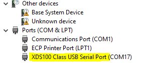
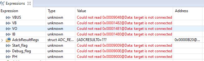
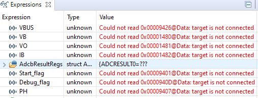
I've been trying to debug my code in CCS 7.3.0.00019 and getting this error every time I operate my power circuit. I am not able to monitor my ADC values because of this error. I tried changing the debug cable, checked JTAG connectivity but still the error appears. Any help to resolve this will be appreciated. Thanks.

C28xx_CPU1: Error: (Error -154 @ 0x0) One of the FTDI driver functions used to write data returned bad status or an error. (Emulation package 7.0.48.0) 

C28xx_CPU1: Trouble Halting Target CPU: (Error -150 @ 0x0) One of the FTDI driver functions used during configuration returned a invalid status or an error. (Emulation package 7.0.48.0)
C28xx_CPU1: Unable to determine target status after 20 attempts
C28xx_CPU1: Failed to remove the debug state from the target before disconnecting. There may still be breakpoint op-codes embedded in program memory. It is recommended that you reset the emulator before you connect and reload your program before you continue debugging
IcePick_C_0: Error: (Error -150 @ 0x0) One of the FTDI driver functions used during configuration returned a invalid status or an error. (Emulation package 7.0.48.0)
IcePick_C_0: Unable to determine target status after 20 attempts
IcePick_C_0: Failed to remove the debug state from the target before disconnecting. There may still be breakpoint op-codes embedded in program memory. It is recommended that you reset the emulator before you connect and reload your program before you continue debugging
C28xx_CPU2: Error: (Error -150 @ 0x0) One of the FTDI driver functions used during configuration returned a invalid status or an error. (Emulation package 7.0.48.0)
C28xx_CPU2: Unable to determine target status after 20 attempts
C28xx_CPU2: Failed to remove the debug state from the target before disconnecting. There may still be breakpoint op-codes embedded in program memory. It is recommended that you reset the emulator before you connect and reload your program before you continue debugging

  • Hi Avishek,

    Can you check the Windows device manager if XDS100v2 is enumerated properly?

    If it does not enumerate, can you install latest emulation package and see if it resolves the issue?

  • Hi Santosh,

    Thanks for your response. This is a snapshot of my device manager:

    I can see XDS100 but not sure what you mean by it enumerating. Can you pls clarify?

    Thanks,

    Avishek

  • Hi Santosh,

    Thanks for your response. This is a snapshot of my device manager:

    I can see XDS100 but not sure what you mean by it enumerating. Can you pls clarify?

    Thanks,

    Avishek

  • Avishek,

    Any update on your issue?

  • Hi Santosh,

    Thanks for the follow-up. As suggested by you, I installed the latest emulation package (V9.2.0.00002) and ran the program. I still see the following errors (154 & 150) in the 'console' and 'expressions' window. The other thing I noticed while running the program, when these errors start popping up I can hear the USB connect/disconnect sound from the PC. Please advise. 

    Console: Run-1 error

    C28xx_CPU1: GEL Output:
    Memory Map Initialization Complete
    C28xx_CPU1: If erase/program (E/P) operation is being done on one core, the other core should not execute from shared-RAM (SR) as they are used for the E/P code. Also, CPU1 will be halted to determine SR ownership for the CPU which will run the Flash Plugin code, after which CPU1 will be set to run its application. User code execution from SR could commence after both flash banks are programmed.
    C28xx_CPU2: GEL Output:
    Memory Map Initialization Complete
    C28xx_CPU2: If erase/program (E/P) operation is being done on one core, the other core should not execute from shared-RAM (SR) as they are used for the E/P code. Also, CPU1 will be halted to determine SR ownership for the CPU which will run the Flash Plugin code, after which CPU1 will be set to run its application. User code execution from SR could commence after both flash banks are programmed.
    C28xx_CPU1: Error: (Error -154 @ 0x0) One of the FTDI driver functions used to write data returned bad status or an error. (Emulation package 9.2.0.00002)
    C28xx_CPU1: Trouble Halting Target CPU: (Error -150 @ 0x0) One of the FTDI driver functions used during configuration returned a invalid status or an error. (Emulation package 9.2.0.00002)
    C28xx_CPU1: Failed to remove the debug state from the target before disconnecting. There may still be breakpoint op-codes embedded in program memory. It is recommended that you reset the emulator before you connect and reload your program before you continue debugging

    Run-2 error:

    C28xx_CPU1: Trouble Reading Memory Block at 0x9048 on Page 1 of Length 0x2: (Error -150 @ 0x0) One of the FTDI driver functions used during configuration returned a invalid status or an error. (Emulation package 9.2.0.00002)
    C28xx_CPU1: Trouble Halting Target CPU: (Error -150 @ 0x0) One of the FTDI driver functions used during configuration returned a invalid status or an error. (Emulation package 9.2.0.00002)
    C28xx_CPU1: JTAG Communication Error: (Error -150 @ 0x0) One of the FTDI driver functions used during configuration returned a invalid status or an error. (Emulation package 9.2.0.00002)
    C28xx_CPU1: Failed to remove the debug state from the target before disconnecting. There may still be breakpoint op-codes embedded in program memory. It is recommended that you reset the emulator before you connect and reload your program before you continue debugging

    ------------------------------------------------------------------------------------------------------------------------------------------------------------------------------------------------

    Thanks,

    Avishek

  • Abhishek,

    Can you go to CCS menu View -> Target Configurations? Launch the configuration and run "Test Connection".

    It looks like FTDI driver is not installed properly. Can you install latest CCS (10.1)? It will also install latest driver.

  • Hi Santosh, 

    I ran the "Test Connection" in CCS 7. Below is the report:

    --------------------------------------------------------------------------------------------------------------

    [Start: Texas Instruments XDS100v2 USB Debug Probe_0]

    Execute the command:

    %ccs_base%/common/uscif/dbgjtag -f %boarddatafile% -rv -o -F inform,logfile=yes -S pathlength -S integrity

    [Result]


    -----[Print the board config pathname(s)]------------------------------------

    C:\Users\ghosha3\AppData\Local\TEXASI~1\
    CCS\ti\0\0\BrdDat\testBoard.dat

    -----[Print the reset-command software log-file]-----------------------------

    This utility has selected a 100- or 510-class product.
    This utility will load the adapter 'jioserdesusb.dll'.
    The library build date was 'May 7 2020'.
    The library build time was '21:07:41'.
    The library package version is '9.2.0.00002'.
    The library component version is '35.35.0.0'.
    The controller does not use a programmable FPGA.
    The controller has a version number of '4' (0x00000004).
    The controller has an insertion length of '0' (0x00000000).
    This utility will attempt to reset the controller.
    This utility has successfully reset the controller.

    -----[Print the reset-command hardware log-file]-----------------------------

    The scan-path will be reset by toggling the JTAG TRST signal.
    The controller is the FTDI FT2232 with USB interface.
    The link from controller to target is direct (without cable).
    The software is configured for FTDI FT2232 features.
    The controller cannot monitor the value on the EMU[0] pin.
    The controller cannot monitor the value on the EMU[1] pin.
    The controller cannot control the timing on output pins.
    The controller cannot control the timing on input pins.
    The scan-path link-delay has been set to exactly '0' (0x0000).

    -----[The log-file for the JTAG TCLK output generated from the PLL]----------

    There is no hardware for programming the JTAG TCLK frequency.

    -----[Measure the source and frequency of the final JTAG TCLKR input]--------

    There is no hardware for measuring the JTAG TCLK frequency.

    -----[Perform the standard path-length test on the JTAG IR and DR]-----------

    This path-length test uses blocks of 64 32-bit words.

    The test for the JTAG IR instruction path-length succeeded.
    The JTAG IR instruction path-length is 6 bits.

    The test for the JTAG DR bypass path-length succeeded.
    The JTAG DR bypass path-length is 1 bits.

    -----[Perform the Integrity scan-test on the JTAG IR]------------------------

    This test will use blocks of 64 32-bit words.
    This test will be applied just once.

    Do a test using 0xFFFFFFFF.
    Scan tests: 1, skipped: 0, failed: 0
    Do a test using 0x00000000.
    Scan tests: 2, skipped: 0, failed: 0
    Do a test using 0xFE03E0E2.
    Scan tests: 3, skipped: 0, failed: 0
    Do a test using 0x01FC1F1D.
    Scan tests: 4, skipped: 0, failed: 0
    Do a test using 0x5533CCAA.
    Scan tests: 5, skipped: 0, failed: 0
    Do a test using 0xAACC3355.
    Scan tests: 6, skipped: 0, failed: 0
    All of the values were scanned correctly.

    The JTAG IR Integrity scan-test has succeeded.

    -----[Perform the Integrity scan-test on the JTAG DR]------------------------

    This test will use blocks of 64 32-bit words.
    This test will be applied just once.

    Do a test using 0xFFFFFFFF.
    Scan tests: 1, skipped: 0, failed: 0
    Do a test using 0x00000000.
    Scan tests: 2, skipped: 0, failed: 0
    Do a test using 0xFE03E0E2.
    Scan tests: 3, skipped: 0, failed: 0
    Do a test using 0x01FC1F1D.
    Scan tests: 4, skipped: 0, failed: 0
    Do a test using 0x5533CCAA.
    Scan tests: 5, skipped: 0, failed: 0
    Do a test using 0xAACC3355.
    Scan tests: 6, skipped: 0, failed: 0
    All of the values were scanned correctly.

    The JTAG DR Integrity scan-test has succeeded.

    [End: Texas Instruments XDS100v2 USB Debug Probe_0]

    ----------------------------------------------------------------------------------------

    Thanks & regards,

    Avishek

  • Avishek,

    Looks like connection test has succeeded.

    Are you able to run any C2000ware DriverLib example code? Are you running into issue on your custom application only?

  • Hi Santosh,

    I installed the latest CCS (Version: 10.1.0.00010) and ran the program. I still see the error while operating my power circuit:

    C28xx_CPU1: JTAG Communication Error: (Error -150 @ 0x0) One of the FTDI driver functions used during configuration returned a invalid status or an error. (Emulation package 9.2.0.00002)
    C28xx_CPU1: Failed to remove the debug state from the target before disconnecting. There may still be breakpoint op-codes embedded in program memory. It is recommended that you reset the emulator before you connect and reload your program before you continue debugging

    Expressions:


    Best regards,

    Avishek

  • Avishek,

    Are you able to run simple C2000ware example and Blinky_led? Are you seeing the issue only in your custom application or simple application also does not work?

  • Hi Santosh, 

    As per your suggestion, I ran the blinky_led code from C2000ware, it works fine. In my application, when I am running the signal circuit (sensors and gate drivers) only, I can see the EPWMs working just fine. But as soon as I turn on the main HV power circuit, I hear the USB connect/disconnect error and see this error.

    Best regards,

    Avishek

  • Avishek,

    What is the JP1 and JP3 setting on your board? I will recommend you to review Launchpad F28379D user's guide section 5.2 for isolated power supply.

    https://www.ti.com/lit/ug/sprui77c/sprui77c.pdf?ts=1597663484222&ref_url=https%253A%252F%252Fwww.google.com%252F

  • Hi Santosh,

    I'm providing external 3.3V to power up the launch pad, using the on-board boost converter to provide 5V (using JP6) and keeping jumper settings for JTAG/USB isolation. So here are my jumper configurations:

    JP1 - No

    JP2 - No

    JP3 - No

    JP6 - Yes

    Thanks & regards,

    Avishek

  • Avishek,

    Despite the isolation is sounds like we are still getting some noise coupling from your active circuit that is putting the FTDI/XDS100v2 into an unknown state, and/or corrupting the JTAG signals into the FTDI chip.

    I think we need to attempt to provide some type of EMI shielding to the area of the PCB that contains the FTDI/USB connection; not sure if you have any EMI gaskets or blockers handy?  It looks like all the major vendors like mouser/Wurth/even Amazon have some varieties of these.  

    I'll see if I can pull some others into this thread to offer their suggestion based on experience.  At the end of the day we may need a more robust/enclosed external JTAG pod that brings the active circuits away from the power/noise source.

    Best,

    Matthew 

  • Hi Mathew,

    Thanks for sharing your insight/advice to resolve the issue. FYI, In my active power circuit I have a HF transformer operating at 50 kHz. I have kept it inside a metal box (Faraday cage) for EMI shielding and placed it physically away from the rest of the electronics on my PCB. I have attached pictures of the setup FYR.

    I had some EMI shielding tape (copper foil) handy. I wrapped it around the area of the launchpad that contains the FTDI/USB connection with proper insulation on the underlying components. I operated my setup with this arrangement. I still hear the USB connect/disconnect sound as soon as I operate the active circuit and see the FTDI driver errors (154 & 150) I shared in the forum earlier. I'm not sure if I did the shielding correctly, awaiting your comments/advice.

    Thanks & regards,

    Avishek


  • Avishek,

    These EMI type issues are always challenging, and change depending on the power electronics topology and board layout.  

    I'd like to determine if the C2000 MCU is still running correctly or only the emulation connection is being effected.

    Is it possible to program the flash with some code that can run the power electronics w/o interaction from CCS?  If we can observe that this can control the system, even when switching, then we can rule out that the EMI is getting into the signal path at the device, and solely at the XDS100v2 interface.

    Best,

    Matthew

  • Hi Mathew,

    Thanks for your response. I just wanted to let you know that I am able to run open loop tests on my power electronics hardware successfully even with the program running in the CPU. I can confirm this by monitoring couple of key waveforms such as the input/output voltage, transformer primary current. The transformer current looks periodic with frequency same as the switching freq. (50kHz) which confirms that the switching signals are not affected. Its just that the JTAG signals are getting corrupted and the emulation is failing to transmit the real-time readings from the sensors to the PC via USB.  

    Best regards,

    Avishek

  • Abhishek,

    You will need to work in Flash mode (JTAG disconnected). I am going to close this thread.