This thread has been locked.

If you have a related question, please click the "Ask a related question" button in the top right corner. The newly created question will be automatically linked to this question.

CCS/TMS320F28379D: How to select desire GPIO/ how to change GPIO pin number for particular signal

Part Number: TMS320F28379D
Other Parts Discussed in Thread: CONTROLSUITE, , POWERSUITE, TIDM-1001

Tool/software: Code Composer Studio

Hello there

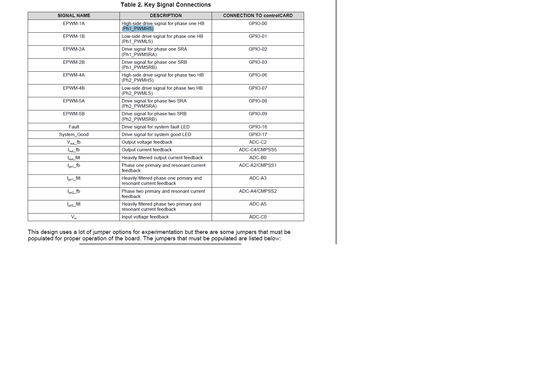
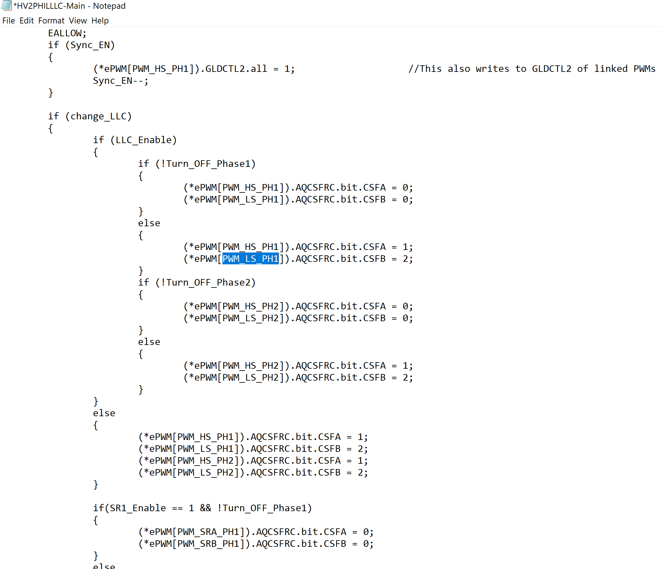
I am working on TIDM 1001. C:\ti\controlSUITE\development_kits\TIDM_1001\v1_00_00_00\f2837x\HV2PHILLLC. I can see the table in the document "TIDUCT9.pdf" location is here C:\ti\controlSUITE\development_kits\TIDM_1001\v1_00_00_00\docs. Table 2. Key Signal connections. It already selected particular GPIO to certain signals. But How can I change it? for that where should I make changes. Is there any tutorial that how to change GPIO in code? I am talking about this table. Also when I observed the code I can't understand how GPIO assigned to particular signal, here as an example I have also shared a screenshot of code related to PWM_LS_PH1, it is not mentioned anywhere that it will connect to GPIO 01. How to understand the selection process of GPIO for particular signal, once I understand this then I can also change it if my application requires.
  • Hi Avi,

    So that I have more context to answer your question, can you explain what you want to enable by changing the GPIO assignments?

    As you've pointed to in table 2 the following assignments were made:

    EPWM1 = phase 1 primary switching

    EPWM2 = phase 2 primary switching

    EPWM3 = generate 50kHz interrupt for the control ISR

    EPWM4 = phase 1 synchronous rectification

    EPWM5 = phase 2 synchronous rectification

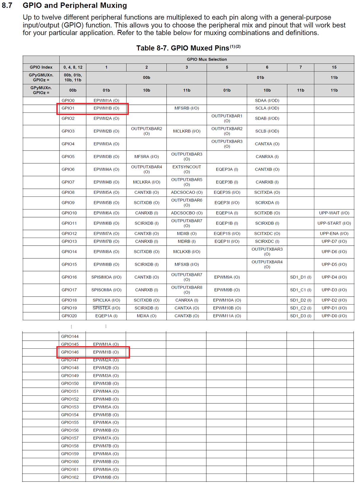
    We usually fill the EPWM modules in ascending order like that (starting from 1 and going up) to ensure best portability from one generation of controlCARDs to the next for our reference designs. After the PWM assignments have been made, then those map to GPIOs using the GPIO mux table in the TRM. (Again, we choose lower GPIO numbers for best portability between devices).

    You can see from the GPIO muxing table that EPWM1-EPWM8 signals can be mapped to GPIO0 - GPIO23, or GPIO145 - GPIO168. On the controlCARD most of the GPIO145 - GPIO168 aren't available, so you will be limited to GPIO0 - GPIO23.

    If want to move the PWM_LS_PH1 signal to a different GPIO you will have to configure a different EPWM to provide that signal.

    Best,

    Clayton

  • Thank you so much Clayton for your depth answer and explanation. I will give the answer first for your question "why change GPIO" so, I will connect 2 systems together and operate in CPU 1 and CPU 2 same time. So I need to make sure that they both don't share the same GPIO otherwise it will be a disaster I guess.

    You gave a splendid answer to my question but I am very new for this technology so still have questions,

    1) In table 2., there are EPWM1-A,  EPWM1-B,  EPWM2-A, EPWM2-B,  EPWM4-A...  EPWM5-B, so how you knew that EPWM 1,2,3,4,5 assigned to mention signals?

    2) I got the picture of how EPWM directly connects with the GPIO selection process. But when I look at the code I can't see any EPWM1B(0) or something. How to read that or how to implement that into code?

    Thanks

    Avi

  • Just so you know, these controlSUITE examples use our old implementation with "bit-field" techniques, but our newer Digital Power SDK examples use the DriverLib approach and I find it a lot easier to understand and the drivers for the peripherals make it easier to set them up. This project is available in Digital Power SDK for the TMS320F28002x devices (these are single CPU devices), but currently there's no port for TMS320F28379D. If you want to use the controlSUITE example as-is, then it's probably a good reference. However, if you plan to write/develop very much of your own code it may be worth looking at the example in the Digital Power SDK.

    Regarding your questions about controlSUITE, I think there are three parts to the answer:

    1. The PWM selection is set in the "HV2PHILLLC_Base-Settings.h" file.

    2. The GPIO configuration happens in the main.c file. This sets GPIO0 to EPWM1-A, etc.

    3. The PWM gets set up to generate the correct PWM outputs by the "PWM_HB_LLC_2PHIL_SR" function. (It sets up EPWM1, EPWM2, EPWM4, EPWM5). You can open the definition of this function and see exactly how it's configuring these PWMs by using the F3 key. It will open the file "PWM_HB_LLC_2PHIL_SR.c".

    Let me know if that helps. Happy Friday :)

  • Thank you so much for the great explanation Clayton, Almost got the picture will work on this.

  • Hi Avi,

    I'm glad it's starting to be a little more clear. Please let me know if you need anything else.

    This project uses the powerSUITE GUI to configure some of it's parameters and I think that will overwrite any changes you make in the "base-settings.h" file. I think before you can actually change the pin assignments I will need to walk you through how to disable powerSUITE for the project. Let me know when you're ready for that step.

    Best,

    Clayton

  • Thank you Clayton for your reply. Yes, you can guide me for that btw this F3 feature is really really helpful thank you for that.

  • Yes, the F3 feature is my favorite shortcut!

    I will need to get in contact with my colleagues and confirm the easiest way to bypass the GUI, and then confirm it on my end. Let me get back to you by end of next week.

    However, you will need to change a few things in the solution to make this work, so I suggest reviewing the material from the F28379D training workshop. The slides and exercises are available here: https://training.ti.com/c2000-f2837xd-microcontroller-workshop

    Also, the material from the digital power training may be useful, especially the seventh video in the series that explains some of the features and challenges of the TIDM-1001 power stage: https://training.ti.com/digitally-controlled-interleaved-llc-resonant-converter-tidm-1001

  • Thank you so much Clayton for the great resources. I will watch this. Again Thank you for the quick positive reply.