This thread has been locked.

If you have a related question, please click the "Ask a related question" button in the top right corner. The newly created question will be automatically linked to this question.

CCS/TMS320F2808: Synchronization of eCap4 and EWM module

Part Number: TMS320F2808


Tool/software: Code Composer Studio

Hello Everyone,

I am trying to generate synchronization pulses for LLC converter.

I measure the AC current from the secondary and using opamp, 0 to 5V pulses are generated at every 0 crossing of the AC current. I am successfully getting these pulses and I measure the frequency of this pulse using ecap4 module.

With this measured frequency I am generating EPWM signals for my MOSFETs, and I do generate the right frequency pulses.

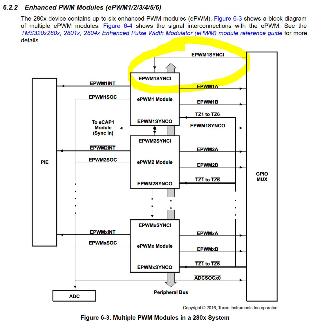
however I am not able to synchronize the ecap4 module with epwm 1 module? Is this possible? If yes, which statement can I use?

Eagerly waiting for an answer.

  • Hi Malvika,

    What event are you trying to synchronize EPWM1 to? Do you want to synchronize it to the zero-crossing?

    Thanks,

    Clayton

  • Hello Clayton,

    Thank you so much for your reply.

    Actually the ecap4 input is the 0 to 5V pulse (occuring at zero crossing). I am measuring the frequency of this pulse and giving the Period value to EPWM1 module. Because my pulses should be synchronized with the frequency of the AC current and also at the zero crossing. so yes I want to synchronize it to the zero crossing. I know there will be a delay because I am first measuring the period and then initializing the EPWM module. But is there any way to synchronize the pulses with ecap4?

    BR

    Malvika

  • Hi Malvika,

    First I want to note that the device has 3.3V I/O, so applying the 5V pulse to the device pins is not recommended. You should probably scale that signal down to 3.3V to avoid any potential problems there.

    The only way to sync the EPWM1 module on an F2808 device is to an external signal coming from a GPIO as you can see in the synchronization figure below. So do you think you can use the zero crossing signal to sync the EPWM1 module, and you can use the measurement from ECAP4 to set the period of EPWM1?

    Best,

    Clayton

  • Hello Clayton,

    This is exactly what I do now. I made a simple program only for synchronization and with some random value of TBPRD. This syncronization program works.

    But when I add the frequency measuring code again, there are no pulses anymore. :(

    Another question is: Can I use the shadow register of TBPRD of EPWM?

    I read somewhere the following:

    "Another unique feature of the F2833x is its “shadow” functionality of operating registers, in the case of ePWM units available for compare register A, B and period register. For some applications it is necessary to modify the values inside a compare or period register, every period. The advantage of the background registers is that we can prepare the values for the next period in the current one. Without a background function we would have to wait for the end of the current period, and then trigger a high prioritized interrupt. Sometimes this form of scheduling will miss its deadline…"

    Maybe this will help save some time?  As the DSP will take 1 complete period to measure the frequency.

    Regards,

    Malvika

  • So now I have frequency measurement done correctly in this code and synchronization with pulses is also ok. The pulses have a TBPRD of the value that I entered and not from the frequency measurement.

    As soon as I enter the TBPRD from the frequency measurement section, it stops giving the pulses.

    So the code looks something like this :

    #include "DSP280x_Device.h"     // DSP280x Header file Include File
    #include "DSP280x_Examples.h"   // DSP280x Examples Include File
    #include "DSP280x_GlobalPrototypes.h"
    #include "DSP280x_SysCtrl.h"

    //Definitions EPWM module
    #define SYSTEM_CLK          100000  //  [kHz]
    #define BRIDGE_PWM_FREQ     80 //   [kHz]; bridge PWM frequency (also change in main.c)
    #define PERIOD              (int)((long)SYSTEM_CLK / (2* BRIDGE_PWM_FREQ))          //  (100MHz / 40kHz)/2 - /2 wegen count up_down
    #define DUTY                (int)((long)SYSTEM_CLK / (4 * BRIDGE_PWM_FREQ))     //  50% Duty Cycle

    //Definitions ECAP module
    // ECCTL1 ( ECAP Control Reg 1)
    //==========================
    // CAPxPOL bits
    #define EC_RISING 0x0
    #define EC_FALLING 0x1
    // CTRRSTx bits
    #define EC_ABS_MODE 0x0
    #define EC_DELTA_MODE 0x1
    // PRESCALE bits
    #define EC_BYPASS 0x0
    #define EC_DIV1 0x0
    #define EC_DIV2 0x1
    #define EC_DIV4 0x2
    #define EC_DIV6 0x3
    #define EC_DIV8 0x4
    #define EC_DIV10 0x5

    // ECCTL2 ( ECAP Control Reg 2)
    //==========================
    // CONT/ONESHOT bit
    #define EC_CONTINUOUS 0x0
    #define EC_ONESHOT 0x1
    // STOPVALUE bit
    #define EC_EVENT1 0x0
    #define EC_EVENT2 0x1
    #define EC_EVENT3 0x2
    #define EC_EVENT4 0x3
    // RE-ARM bit
    #define EC_ARM 0x1
    // TSCTRSTOP bit
    #define EC_FREEZE 0x0
    #define EC_RUN 0x1
    // SYNCO_SEL bit
    #define EC_SYNCIN 0x0
    #define EC_CTR_PRD 0x1
    #define EC_SYNCO_DIS 0x2
    // CAP/APWM mode bit
    #define EC_CAP_MODE 0x0
    #define EC_APWM_MODE 0x1
    // APWMPOL bit
    #define EC_ACTV_HI 0x0
    #define EC_ACTV_LO 0x1
    // Generic
    #define EC_DISABLE 0x0
    #define EC_ENABLE 0x1
    #define EC_FORCE 0x1

    // Prototype statements for functions found within this file
    void Gpio_select(void);
    void Setup_ePWM1A(void);
    void Setup_eCAP4(void);

    //Interrupt routines
    interrupt void cpu_timer0_isr(void);
    interrupt void eCAP4_isr(void);

    // Variables for ECAP module
    Uint32 TSt1 = 0;
    Uint32 TSt2 = 0;
    Uint32 TSt3 = 0;
    Uint32 TSt4 = 0;
    Uint32 Period1 = 0;
    Uint32 Period2 = 0;
    Uint32 Period3 = 0;

    //###########################################################################
    //                      main code
    //###########################################################################
    void main(void)
    {
      //  int counter=0;  // binary counter for digital output

        InitSysCtrl();  // Basic Core Init from DSP280x_SysCtrl.c
        EALLOW;
        SysCtrlRegs.PCLKCR1.bit.ECAP4ENCLK = 1;  // eCAP4 clock initialization
        EDIS;
        MemCopy(&RamfuncsLoadStart, &RamfuncsLoadEnd, &RamfuncsRunStart);
        InitFlash();

    /*// statements below create error in EPWM signal
        EALLOW;
        SysCtrlRegs.WDCR= 0x00AF;   // Re-enable the watchdog
        EDIS;           // 0x00AF  to NOT disable the Watchdog, Prescaler = 64
    */

        DINT;               // Disable all interrupts

        Gpio_select();      //Initialization of GPIO

        Setup_eCAP4();      //Initialization of ECAP4

        InitPieCtrl();      // basic setup of PIE table; from DSP2833x_PieCtrl.c

        InitPieVectTable(); // default ISR's in PIE

        EALLOW;
        PieVectTable.TINT0 = &cpu_timer0_isr;
        PieVectTable.ECAP4_INT= &eCAP4_isr;
        EDIS;

        InitCpuTimers();    // basic setup CPU Timer0, 1 and 2

        ConfigCpuTimer(&CpuTimer0,100,100000);

        PieCtrlRegs.PIEIER1.bit.INTx7 = 1; //Enable CPU Timer 0 INT
        PieCtrlRegs.PIEIER4.bit.INTx4 = 1; //Enable ECAP1_INT in PIE group 4

        //IER |= 1;
        IER |= 0x0009; //works for only  ecap4

        EINT;
        ERTM;

        CpuTimer0Regs.TCR.bit.TSS = 0;  // start timer0

    /*    for(;;)
        {
            asm("          NOP");
        }*/

       Setup_ePWM1A();     //Initialization of ePWM1A

       while(1)
       {
               while(CpuTimer0.InterruptCount == 0);
                CpuTimer0.InterruptCount = 0;

                EALLOW;
                SysCtrlRegs.WDKEY = 0x55;   // service WD #1
                EDIS;

    //            counter++;

    }
    }
    void Gpio_select(void)
    {
        EALLOW;
        GpioCtrlRegs.GPAMUX1.all = 0;       // GPIO15 ... GPIO0 = General Puropse I/O
        GpioCtrlRegs.GPAMUX1.bit.GPIO0 = 1; // ePWM1A active
        GpioCtrlRegs.GPADIR.bit.GPIO0 = 1; // as output

        //initialization for GPIO11/ eCAP4 as input pin
        GpioCtrlRegs.GPAPUD.bit.GPIO11 = 1;
        GpioCtrlRegs.GPACTRL.bit.QUALPRD1 = 0x02;
        GpioCtrlRegs.GPAQSEL1.bit.GPIO11 = 2;        // XINT1 Qual using 6 samples
        GpioCtrlRegs.GPAMUX1.bit.GPIO11 = 3;
        GpioCtrlRegs.GPADIR.bit.GPIO11 = 0; // as input

        //initialization for GPIO6 as input pin for EPWM Sync-In
        GpioCtrlRegs.GPAPUD.bit.GPIO6 = 0;
        GpioCtrlRegs.GPAMUX1.bit.GPIO6 = 2; //EPWMSYNCI, ePWM Synch-in
        GpioCtrlRegs.GPADIR.bit.GPIO6 = 0; // as input

        EDIS;
    }


    interrupt void cpu_timer0_isr(void)
    {
        CpuTimer0.InterruptCount++;
        EALLOW;
        SysCtrlRegs.WDKEY = 0xAA;   // service WD #2
        EDIS;
        PieCtrlRegs.PIEACK.all = PIEACK_GROUP1;
    }

    void Setup_eCAP4(void)
    {
    //---------------------------------------------------------------------
    //--- Configure eCAP4 unit for capture
    //---------------------------------------------------------------------
        ECap4Regs.ECEINT.all = 0;                   // Disable all eCAP interrupts
        ECap4Regs.ECCLR.all = 0xFFFF;       // clear all interrupt flags //new addition

        ECap4Regs.ECCTL1.bit.CAPLDEN = 0;           // Disabled loading of capture results
        ECap4Regs.ECCTL2.bit.TSCTRSTOP = 0;         // Stop the counter

        ECap4Regs.TSCTR = 0;                        // Clear the counter
        ECap4Regs.CTRPHS = 0;                       // Clear the counter phase register


        // Initialization Time
        //=======================
        // ECAP module 4 configuration
        ECap4Regs.ECCTL1.bit.FREE_SOFT = 0; //TSCTR stops immediately on emulation suspend
        ECap4Regs.ECCTL1.bit.CAP1POL = EC_RISING; //capture event polarity select
        ECap4Regs.ECCTL1.bit.CAP2POL = EC_RISING;
       // ECap4Regs.ECCTL1.bit.CAP3POL = EC_RISING;
       // ECap4Regs.ECCTL1.bit.CAP4POL = EC_RISING;
        ECap4Regs.ECCTL1.bit.CTRRST1 = EC_ABS_MODE; //counter reset on capture event 1
        ECap4Regs.ECCTL1.bit.CTRRST2 = EC_ABS_MODE; //counter reset on capture event 2
       // ECap4Regs.ECCTL1.bit.CTRRST3 = EC_ABS_MODE; //counter reset on capture event 3
       // ECap4Regs.ECCTL1.bit.CTRRST4 = EC_ABS_MODE; //counter reset on capture event 4
        ECap4Regs.ECCTL1.bit.CAPLDEN = EC_ENABLE; //enable loading of CAP1-4 registers on capture event
        ECap4Regs.ECCTL1.bit.PRESCALE = EC_DIV1; //event filter prescale select

        ECap4Regs.ECCTL2.bit.CAP_APWM = EC_CAP_MODE; //capture mode
        ECap4Regs.ECCTL2.bit.SYNCO_SEL = EC_SYNCO_DIS;// 0;
        ECap4Regs.ECCTL2.bit.SYNCI_EN = EC_DISABLE;
        ECap4Regs.ECCTL2.bit.TSCTRSTOP = EC_RUN; // Allow TSCTR to run
        // ECap4Regs.ECCTL2.bit.REARM = 1; //Arms 1-shot sequence, resets Mod4 counter to 0, unfreezes the mod4 counter, enable cap register loads
        ECap4Regs.ECCTL2.bit.STOP_WRAP = 2; // Stop after Capture Event 4 in one-shot mode
        ECap4Regs.ECCTL2.bit.CONT_ONESHT = EC_ONESHOT;

        //ECAP Interrupt Enable Register
        ECap4Regs.ECEINT.bit.CEVT3 =1;

        }

    interrupt void eCAP4_isr(void)
    {
        ECap4Regs.ECCLR.bit.INT = 1;                // Clear the ECAP4 interrupt flag
        ECap4Regs.ECCLR.bit.CEVT3 = 1;              // Clear the CEVT4 flag

        // Run Time ( e.g. CEVT4 triggered ISR call)
        //==========================================
        TSt1 = ECap4Regs.CAP1; // Fetch Time-Stamp captured at t1
        TSt2 = ECap4Regs.CAP2; // Fetch Time-Stamp captured at t2
        TSt3 = ECap4Regs.CAP3; // Fetch Time-Stamp captured at t3
      //  TSt4 = ECap4Regs.CAP4; // Fetch Time-Stamp captured at t4

        Period1 = TSt2-TSt1; // Calculate 1st period
        Period2 = TSt3-TSt2; // Calculate 2nd period
      //  Period3 = TSt4-TSt3; // Calculate 3rd period


        PieCtrlRegs.PIEACK.all = PIEACK_GROUP4; // Must acknowledge the PIE group 4
    }

    void Setup_ePWM1A(void)
    {   EPwm1Regs.TZCTL.all =  0;
        EPwm1Regs.TBCTL.bit.CLKDIV =  0;    // CLKDIV = 1
        EPwm1Regs.TBCTL.bit.HSPCLKDIV = 0;  // HSPCLKDIV = 2
        EPwm1Regs.TBCTL.bit.CTRMODE = 2;    // up - down mode

        EPwm1Regs.TBPRD = Period1;            // 80KHz - PWM signal
        EPwm1Regs.CMPA.half.CMPA  = Period1/2;      // 100% duty cycle first
        EPwm1Regs.AQCTLA.bit.CAU = 0x1;             // Set PWM1A on Zero
        EPwm1Regs.AQCTLA.bit.CAD = 0x2;

        // EPwm1Regs.AQCTLA.all = 0x0006;      // ZRO = set, PRD = clear
          //for synchronization
          // EPwm1Regs.TBCTL.bit.FREE_SOFT=1; //Stop when counter completes a whole cycle
           EPwm1Regs.TBCTL.bit.PHSDIR=1;
           EPwm1Regs.TBCTL.bit.SYNCOSEL=0;
         //  EPwm2Regs.TBCTL.bit.SYNCOSEL=0;
       //    EPwm1Regs.TBCTL.bit.SWFSYNC=1; //force one-time sync
           EPwm1Regs.TBCTL.bit.PHSEN=1; // CTR=TBPHS on EPWMxSYNCI signal
        //   EPwm1Regs.TBSTS.bit.SYNCI=1; //sync has occured
          // EPwm1Regs.AQCTLA.all = 0x0006;      // ZRO = set, PRD = clear

    }

    //===========================================================================
    // End of SourceCode.
    //===========================================================================

    Should I put the Setup_ePWM1A in the Interrupt program from Ecap?

    Do you have some ideas?


    Thanking you

  • Hi Malvika,

    Sorry for the delay in getting back to you.

    1. Yes, you can enable the shadow register for TBPRD and CMPA. I think it will help in your application.
    2. I think it's fine to leave the Setup_EPWM1A function call in main(), but you will need to add lines somewhere that update the TBPRD and CMPA registers. You may be able to add that in the eCAP4_isr().

    I hope you've made some progress. Please let me know.

    Best,

    Clayton

  • Hi Clayton,

    Thank you for your reply :).

    I do something as shown in the diagram in the attached photo. And now it works :)

    When I change frequency then frequency of pulse also changes.

    But now there are more tasks to do like generating the rest of the pulses for EPWM1B, 2A and 2B.

    There is also a question that the DSP will atleast take 1 period of the original pulse to measure the frequency, so will happen to my synchronous rectification process during that 1 period. So my AC current frequency has changed from say worst case to 90kHz from 80Khz and my generated pulse is still 80Khz. Does this create a problem?

    I am trying to figure out these things.

    Regards,

    Malvika

  • Hi Malvika,

    Can you attach the diagram you mentioned? You have to use the "Insert/Edit Media" option on the toolbar to attach images in your post. If you simply paste them into the textbox they will not show after you post.

    Best,

    Clayton