


Part Number: TMS320F28379D
Hello,
I am actually trying to control an electric drive with one of your Dual-CPU Delfino Launchpads.To do so, I am exploiting the Matlab Code Composer, so I am doing the programming in Simulink.
My general actual approach is to implement speed control on CPU1, and to implement current control CPU2. This will of course communicate via the IPC interface.
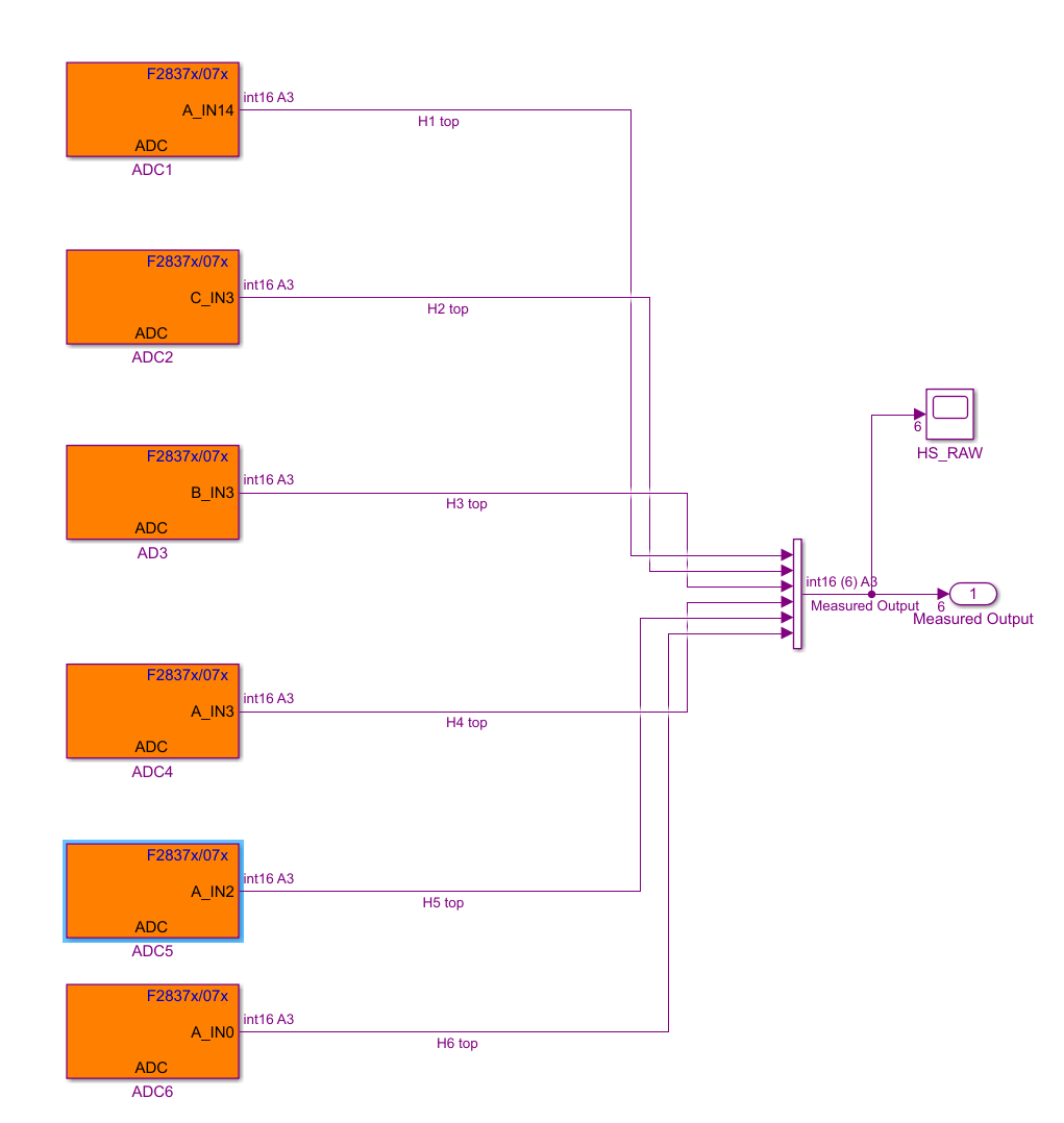
For the speed control, I have a 5 kHz ePWM interrupt, which generates an SOCA and SOCB, which reads the values of 6 hall sensors onto the ADCs.
Given that the ADC-A module is used multiple times, the SOC sequences is correspondly increased. On the other hand, ADC-B and ADC-C are tapped only once, so both are read at SOC0.
This is done by CPU1, and it works perfectly. It can be seen below.
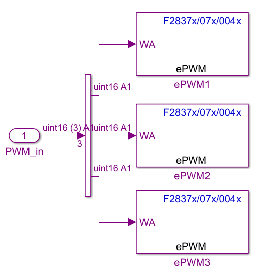
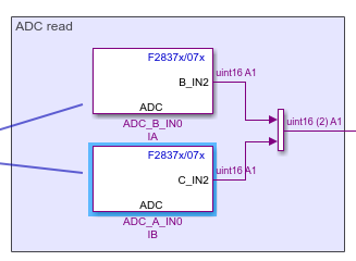
As mentioned, I intend to control the current on CPU2. I use interrupt ePWM7 to launch the routine at 45 kHz. Inside the routine, the PWM 1- 2-3 modules from below, also switching at 45 kHz, generate their respective SOCA and SOCB to read the currents on ADC modules B and C.
I am now trying to test the current control and the sampling of the hall sensors at the same time.
The hall sensors from the the first picture can always be read with success. The problem arises when testing the current control.
The PWM modules for the current generate the SOCA and SOCB triggers that should be controlling the ADCs from above. If they are sampled with the same SOC than the hall sensors from CPU1, I end up reading their value, and not the value of the current. That I understand. Nevertheless, if I set them to sample with the subsequent SOC value, they do not sample at all... Thus the current control does not work.
Funnily enough, if I comment the ADC-B and ADC-C of the hall sensors (that is from CPU1), the currents are correctly sampled in CPU2. It is the same thing when I try running both routines on the same CPU : it actually works.
Does anyone have ideas to how I can correctly configure the ADCs so that the CPU1 and CPU2 can correctly share them ?
Thanks in advance,
Patricio

