This thread has been locked.

If you have a related question, please click the "Ask a related question" button in the top right corner. The newly created question will be automatically linked to this question.

TMS320F280049: ePWMs synchronization TBCNT delay

Part Number: TMS320F280049


Hi Experts,

A customer configured that ePWM1 is the master and ePWM2 to 6 are the slave.
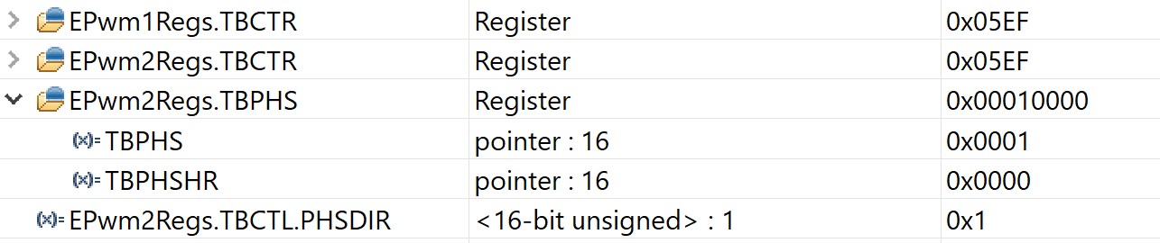
And then the TBCNTs for each ePWM was captured and there confirmed 2 clocks differences between the master and the slaves.

When TBPHS=2 was set to the ePWM2 to 6 which are slaves, 4 clock differences confirmed.

I believe that TBCNTs for ePWMs are synchronized if TBPSH=2 for the salves.
So could you please check the correct method and let me know what I should check their settings.

Thank you for your kind support.
Best regards,TI_F280049_ePWM1to6_Sync_TBCNT.pdf
Hitoshi


  • Hitoshi Sugawara said:
    When TBPHS=2 was set to the ePWM2 to 6 which are slaves, 4 clock differences confirmed.

    I believe that TBCNTs for ePWMs are synchronized if TBPSH=2 for the salves.
    So could you please check the correct method and let me know what I should check their settings.

    So when you TBPHS=2, are the TBCTRs synced or are they 4 off?

  • Hi Nima,

    Let me clarify how to confirm if a master and slaves are synchronized or not.
    If TBCTRs are the same for each ePWM, is it synchronized?

    Thank you for your kind check.
    Best regards,
    Hitoshi 

  • Yes depending on the type of synchronization you want. Some people want 180degrees offset sync. For your case, I believe you are looking for the same TBCTR.

  • Hi Nima,

    Thank you for your kind help.
    Will check the TBCTR.

    Best regards,
    Hitoshi

  • Hitoshi,

    Any feedback from customer?

    Nima

  • Hi Nima,

    The ePWM configuration was attached.
    Could you please look into it?
    If TBPHS = 2, TBCTR difference is 4.

    Thank you for your kind check.
    Best regards,
    HitoshiF280049_ePWM_sync_TBCTR.pdf

  • Okay then in that case, if you want both to be synced you may have to set the TBPHS=PRD-2.

    Nima

  • Hi Nima,

    Thank you for your check.
    Let us try the TBPHS=PRD-2.

    will come back soon.
    Best regards,
    Hitoshi

  • Hi Nima,

    They are utilizing Up-Down mode.
    It seems it is not possible to set TBPHS = PRD-2.

    I would like to try it at my side.
    Are there any sample code available for checking the condition?

    Thank you and best regards,
    Hitoshi 

  • Unfortunately no example, but I'll ask to see if I can find one.

    Nima

  • Hitoshi,

    Possibly the answer to your question is using TBPHS = 2, and also using the TBCTL.PHSDIR = 0 (count down).

    The TBCTL.PHSDIR, determines the phase after the sync event is received. In that case, when the SYNC occurs, the counter is counting down from 2 to zero first synchronizing the two.

    Nima

  • Here is the final, VERIFIED on both the scope, and on the debugger. PERFECT sync, for both up count and up-down count.

    //#############################################################################
    //
    // FILE:   epwm_ex14_zero_phase.c
    //
    // TITLE:  ePWM Using The Synch Chain and Phase Shift.
    //
    //! \addtogroup driver_example_list
    //! <h1>ePWM Synchronization</h1>
    //!
    //! This example configures ePWM1, ePWM2 as follows
    //!  - ePWM1 without phase shift as master
    //!  - ePWM2 with phase shift of 0 TBCLKs
    //!
    //! \b External \b Connections \n
    //! - GPIO0 EPWM1A
    //! - GPIO1 EPWM1B
    //! - GPIO2 EPWM2A
    //! - GPIO3 EPWM2B
    //!
    //! \b Watch \b Variables \n
    //! - None.
    //
    //#############################################################################
    // $TI Release: $
    // $Release Date: $
    // $Copyright: $
    //#############################################################################
    
    //
    // Included Files
    //
    #include "driverlib.h"
    #include "device.h"
    #include "board.h"
    
    #define USE_UPDOWN_COUNT    1
    
    #define EPWM_TIMER_TBPRD    2000
    
    //
    // Function Prototypes
    //
    void initEPWM(uint32_t base);
    
    __interrupt void epwm1ISR(void);
    __interrupt void epwm2ISR(void);
    
    //
    // Main
    //
    void main(void)
    {
        //
        // Initialize device clock and peripherals
        //
        Device_init();
    
        //
        // Disable pin locks and enable internal pull ups.
        //
        Device_initGPIO();
    
        //
        // Initialize PIE and clear PIE registers. Disables CPU interrupts.
        //
        Interrupt_initModule();
    
        //
        // Initialize the PIE vector table with pointers to the shell Interrupt
        // Service Routines (ISR).
        //
        Interrupt_initVectorTable();
    
        //
        // Assign the interrupt service routines to ePWM interrupts
        //
        Interrupt_register(INT_EPWM1, &epwm1ISR);
        Interrupt_register(INT_EPWM2, &epwm2ISR);
    
        //
        // Configure GPIO0/1 , GPIO2/3 and GPIO4/5 and GPIO6/7 as
        // ePWM1A/1B, ePWM2A/2B, ePWM3A/3B, ePWM4A/4B pins respectively
        //
        Board_init();
    
        // Disable sync(Freeze clock to PWM as well). GTBCLKSYNC is applicable
        // only for multiple core devices. Uncomment the below statement if
        // applicable.
        //
        // SysCtl_disablePeripheral(SYSCTL_PERIPH_CLK_GTBCLKSYNC);
        SysCtl_disablePeripheral(SYSCTL_PERIPH_CLK_TBCLKSYNC);
    
        //
        // Initialize PWM1 without phase shift as master
        //
        initEPWM(myEPWM1_BASE);
    
        //
        // Initialize PWM2 with phase shift of 300 TBCLKs
        //
        initEPWM(myEPWM2_BASE);
        EPWM_selectPeriodLoadEvent(myEPWM2_BASE, EPWM_SHADOW_LOAD_MODE_SYNC);
    #if USE_UPDOWN_COUNT == 0
        EPWM_setPhaseShift(myEPWM2_BASE, 1);
    #else
        EPWM_setPhaseShift(myEPWM2_BASE, 1);
        EPWM_setCountModeAfterSync(myEPWM2_BASE, EPWM_COUNT_MODE_UP_AFTER_SYNC);
    #endif
        EPWM_setTimeBaseCounter(myEPWM2_BASE, 0);
    
    
        //
        // ePWM1 SYNCO is generated on CTR=0
        //
        EPWM_setSyncOutPulseMode(EPWM1_BASE, EPWM_SYNC_OUT_PULSE_ON_COUNTER_ZERO);
    
        //
        // ePWM2 uses the ePWM 1 SYNCO as its SYNCIN.
        // ePWM2 SYNCO is generated from its SYNCIN, which is ePWM1 SYNCO
        //
        EPWM_setSyncOutPulseMode(myEPWM2_BASE, EPWM_SYNC_OUT_PULSE_ON_EPWMxSYNCIN);
    
        //
        // Enable all phase shifts.
        //
        EPWM_enablePhaseShiftLoad(myEPWM2_BASE);
    
        //
        // Enable sync and clock to PWM
        //
        SysCtl_enablePeripheral(SYSCTL_PERIPH_CLK_TBCLKSYNC);
    
        //
        // Enable ePWM interrupts
        //
        Interrupt_enable(INT_EPWM1);
        Interrupt_enable(INT_EPWM2);
    
        //
        // Enable Global Interrupt (INTM) and realtime interrupt (DBGM)
        //
        EINT;
        ERTM;
    
        //
        // IDLE loop. Just sit and loop forever (optional):
        //
        for(;;)
        {
    
        }
    }
    
    //
    // epwm1ISR - ePWM 1 ISR
    //
    __interrupt void epwm1ISR(void)
    {
        //
        // Clear INT flag for this timer
        //
        EPWM_clearEventTriggerInterruptFlag(myEPWM1_BASE);
    
        //
        // Acknowledge interrupt group
        //
        Interrupt_clearACKGroup(INTERRUPT_ACK_GROUP3);
    }
    
    //
    // epwm2ISR - ePWM 2 ISR
    //
    __interrupt void epwm2ISR(void)
    {
        //
        // Clear INT flag for this timer
        //
        EPWM_clearEventTriggerInterruptFlag(myEPWM2_BASE);
    
        //
        // Acknowledge interrupt group
        //
        Interrupt_clearACKGroup(INTERRUPT_ACK_GROUP3);
    }
    
    void initEPWM(uint32_t base)
    {
        //
        // Set-up TBCLK
        //
        EPWM_setTimeBasePeriod(base, EPWM_TIMER_TBPRD);
        EPWM_setPhaseShift(base, 0U);
        EPWM_setTimeBaseCounter(base, 0U);
    
        //
        // Set Compare values
        //
        EPWM_setCounterCompareValue(base,
                                    EPWM_COUNTER_COMPARE_A,
                                    EPWM_TIMER_TBPRD/2);
        EPWM_setCounterCompareValue(base,
                                    EPWM_COUNTER_COMPARE_B,
                                    EPWM_TIMER_TBPRD/4);
    
        //
        // Set up counter mode
        //
    #if USE_UPDOWN_COUNT == 0
        EPWM_setTimeBaseCounterMode(base, EPWM_COUNTER_MODE_UP);
    #else
        EPWM_setTimeBaseCounterMode(base, EPWM_COUNTER_MODE_UP_DOWN);
    #endif
    
        EPWM_disablePhaseShiftLoad(base);
        EPWM_setClockPrescaler(base,
                               EPWM_CLOCK_DIVIDER_8,
                               EPWM_HSCLOCK_DIVIDER_1);
    
        //
        // Set up shadowing
        //
        EPWM_setCounterCompareShadowLoadMode(base,
                                             EPWM_COUNTER_COMPARE_A,
                                             EPWM_COMP_LOAD_ON_CNTR_ZERO);
        EPWM_setCounterCompareShadowLoadMode(base,
                                             EPWM_COUNTER_COMPARE_B,
                                             EPWM_COMP_LOAD_ON_CNTR_ZERO);
    
        //
        // Set actions
        //
        EPWM_setActionQualifierAction(base,
                                      EPWM_AQ_OUTPUT_A,
                                      EPWM_AQ_OUTPUT_HIGH,
                                      EPWM_AQ_OUTPUT_ON_TIMEBASE_ZERO);
        EPWM_setActionQualifierAction(base,
                                      EPWM_AQ_OUTPUT_B,
                                      EPWM_AQ_OUTPUT_HIGH,
                                      EPWM_AQ_OUTPUT_ON_TIMEBASE_ZERO);
        EPWM_setActionQualifierAction(base,
                                      EPWM_AQ_OUTPUT_A,
                                      EPWM_AQ_OUTPUT_LOW,
                                      EPWM_AQ_OUTPUT_ON_TIMEBASE_UP_CMPA);
        EPWM_setActionQualifierAction(base,
                                      EPWM_AQ_OUTPUT_B,
                                      EPWM_AQ_OUTPUT_LOW,
                                      EPWM_AQ_OUTPUT_ON_TIMEBASE_UP_CMPB);
    
    
        //
        // Interrupt where we will change the Compare Values
        // Select INT on Time base counter zero event,
        // Enable INT, generate INT on 1rd event
        //
        EPWM_setInterruptSource(base, EPWM_INT_TBCTR_ZERO);
        EPWM_enableInterrupt(base);
        EPWM_setInterruptEventCount(base, 1U);
    }
    

    UP COUNT Results

    UP-DOWN COUNT Results

  • Hi Nima,

    Thank you so much for your creating the sample code.
    The customer could confirm the synchronization of the TBCTRs.

    We very appreciate your kind support.
    Best regards,
    Hitoshi

  • Hitoshi,

    You are welcome!

    I will close the thread.

    Nima