This thread has been locked.

If you have a related question, please click the "Ask a related question" button in the top right corner. The newly created question will be automatically linked to this question.

CCS/TMS320F280049: Configure OTP registers to Boot from Flash, DSP controller locked

Part Number: TMS320F280049
Other Parts Discussed in Thread: UNIFLASH

Tool/software: Code Composer Studio

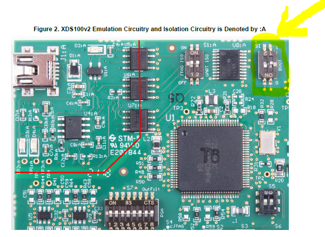
I am having an issue with BOOT mode of the controller. I followed the steps in this thread:

https://e2e.ti.com/support/microcontrollers/c2000/f/171/t/810249

Something we are not totally sure is if after programming OTP registers we are still able to debug using code composer, we did this change to our command linker file (cmd):

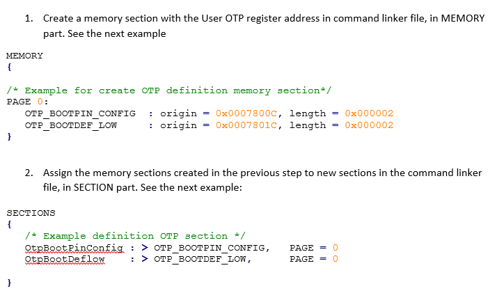
We have understood that we only need to change the values for 2 registers, the BOOTPIN_CONFIG and the BOOTDEF_LOW, to change them we run the following step:

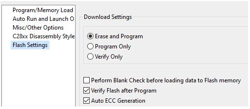
Our final goal was to make the controller boot from flash since whenever you do a power cycle of the unit, the main application does not run. After loading this code we got the following error:

It seems the controller got locked and we couldn't unlock it. Could it be that the way we configured the OTP registers is wrong and by doing what we did we locked it?

  • Omar,

    User "WaitBOOT" mode (refer TRM to see the detail on WaitBOOT)  to connect CCS to device and then see what setting got programed in in USER OTP. 

    Regards,

    Vivek Singh

  • Hi Vivek,

    Thanks for the response, we are using the eval board of the controller to test this, we already tried setting "WaitBOOT" or that is what we think.

    We set switch S1 as follows:

    The yellow arrow shows the Switch we set to OFF for GPIO24 and ON for GPIO32. Then we tried to connect with code composer but we still get an error and we are unable to connect. We can Launch, we can see how CCS configures the debugger XDS100, but can't connect to the controller:

    I was also wondering, if the OTP registers are programmed, then shouldn't all BMS pins be disabled:

  • Omar,

     I was also wondering, if the OTP registers are programmed, then shouldn't all BMS pins be disabled:

    If you have used the option to disable all BOOTMODE pins then yes, changing the BOOTMODE from pin have no meaning. I am afraid that in such case you may not be able to use the device if not able to connect and only solution would be to replace the device/board. You always need to use emulation BOOT to make sure setting you are planning are working with application and only at the end should program the OTP location.

    I am still surprised that if you have not programmed the security settings then why device is locked. Can you attach you .map file from compiler output ? 

    Regards,

    Vivek Singh

  • Sure, here is map:

    7851.DSP.txt
    Fullscreen
    1
    2
    3
    4
    5
    6
    7
    8
    9
    10
    11
    12
    13
    14
    15
    16
    17
    18
    19
    20
    21
    22
    23
    24
    25
    26
    27
    28
    29
    30
    31
    32
    33
    34
    35
    36
    37
    38
    39
    40
    41
    42
    43
    44
    ******************************************************************************
    TMS320C2000 Linker PC v20.2.1
    ******************************************************************************
    >> Linked Fri Oct 23 15:38:04 2020
    OUTPUT FILE NAME: <DSP.out>
    ENTRY POINT SYMBOL: "code_start" address: 00080000
    MEMORY CONFIGURATION
    name origin length used unused attr fill
    ---------------------- -------- --------- -------- -------- ---- --------
    PAGE 0:
    RAMLS0 00008000 00000800 00000002 000007fe RWIX
    RAMLS1 00008800 00000800 00000002 000007fe RWIX
    RAMLS2 00009000 00000800 00000002 000007fe RWIX
    RAMLS3 00009800 00000800 00000002 000007fe RWIX
    RAMLS4 0000a000 00000800 00000002 000007fe RWIX
    RAMLS5 0000a800 00000800 00000002 000007fe RWIX
    RAMLS6 0000b000 00000800 00000002 000007fe RWIX
    RAMLS7 0000b800 00000800 00000002 000007fe RWIX
    OTP_BOOTPIN_CONFIG 0007800c 00000002 00000002 00000000 RWIX
    OTP_BOOTDEF_LOW 0007801c 00000002 00000002 00000000 RWIX
    BEGIN_FLASH 00080000 00000008 00000002 00000006 RWIX (ffff)
    FLASH_BANK0_SEC0 00080008 00000ff8 00000000 00000ff8 RWIX (ffff)
    FLASH_BANK0_SEC1_15 00081000 0000efc0 000021de 0000cde2 RWIX (ffff)
    SWIDENT 0008ffc0 00000040 00000000 00000040 R (ffff)
    FLASH_BANK1_SEC0_15 00090000 00010000 00000000 00010000 RWIX (ffff)
    RESET 003fffc0 00000002 00000000 00000002 R
    BEGIN_FLASH_ECC 01080000 00000001 00000001 00000000 RWIX
    FLASH_BANK0_SEC0_ECC 01080001 000001ff 000001ff 00000000 RWIX
    FLASH_BANK0_SEC1_15_E 01080200 00001df8 00001df8 00000000 RWIX
    SWIDENT_ECC 01081ff8 00000008 00000008 00000000 RWIX
    FLASH_BANK1_SEC0_15_E 01082000 00002000 00002000 00000000 RWIX
    PAGE 1:
    BOOT_RSVD 00000000 000000f1 00000000 000000f1 RWIX
    RAMM0 000000f3 0000030c 00000088 00000284 RWIX
    RAMM1 00000400 000003ff 000003aa 00000055 RWIX
    RAMGS0 0000c000 00002000 00000415 00001beb RWIX
    RAMGS1 0000e000 00002000 00001002 00000ffe RWIX
    RAMGS2 00010000 00002000 00001002 00000ffe RWIX
    RAMGS3 00012000 00002000 00000002 00001ffe RWIX
    XXXXXXXXXXXXXXXXXXXXXXXXXXXXXXXXXXXXXXXXXXXXXXXXXX

    I wonder if the OTP was programmed to boot from flash as we think we did, should we be able to debug and load program, or by booting from flash would it also disabled those options?

  • Map file look ok. What have you programmed in flash ? Is it a working code ?

  • Yes it is a working code, we just programmed those OTP register as I showed in the first message of this thread and then we couldn't access anymore the controller.

    Do you have any other idea on what the problem could be?

  • Omar,

    I don't see why programming BOOT setting should cause issue to connect to device unless something got programmed into other security settings.

    How are you trying to connect to CCS ? Are you launching the target configuration file and then manually connecting to target or clicking on "Debug" which launches the CCS and also loads the code ?

    Regards,

    Vivek Singh

  • Vivek,

    We couldn't find what the issue was! we didn't touch any security settings. The code we have works correctly, the only changes we did were those in the CMD file and in the code I have showed in the first message of this thread. We launch and then manually connect to the controller we didn't use "Debug".

    We are testing another method in other unit. We are going to instead of programming the OTP registers going to use the Boot pins that by default are GPIO24/GPIO32 connected to SW 1 in the Piccolo controlCARD, according to spruic4a. So setting them both up.

    After setting this we found that the code still doesn't boot from flash. We suspect it does but there might be an error that is making it fail so we don't see the heartbeat blinking. We experimented this same method using one of the Labs in the "driverLib" examples for C2000. We found that the code is booting from flash. We still don't find what difference between the codes is making our project crash.

    We found that by disabling the AutoECC in Lab 10 ("which we have disabled in our project"), as well as all related ECC verification or test functions, it would have a similar behavior and the LED doesn't blink. Do you know if the ECC module is involved in the execution of the code if it is disabled?

  • Omar,

    I am looping in Vamsi, our flash expert to look into this. I think if you disbale AutoECC then ECC will not be programmed and you have to program ECC separately. Failing to do so will cause issue when you program the OTP setting. That may be the reason why you are not able to connect to CCS.

    Regards,

    Vivek Singh

  • Omar,

    AutoEccGeneration when enabled calculates and programs ECC for the flash and OTP contents when you load the code.  Hence, it is important to keep this enabled.  If ECC is not programmed, application will end up in ECC errors (and hence NMI/resets) since ECC check is enabled by default in the device.

    Please let us know if you have any specific question on ECC.

    Thanks and regards,
    Vamsi

  • Vamsi,

    Thank you for the thread follow up. As I mentioned to Vivek we are trying a second method to make it boot from flash. For the first method we failed and we are not sure how to reconnect to the controller. In this second method we have two programming options, one with CCS and the other with Uniflash. In both cases there is an option to enable AutoECC:

    CCS enable AutoECC OptionUniflash enable AutoECC Option

    As you can see both cases are very similar. However, we have issues loading SW with CCS. When we use Uniflash we get no errors:

    However, when we use CCS we get the following errors:

    1 - So our first doubt is, what is the difference between Uniflash and CCS that by enabling the AutoECC the same way we can't program using CCS?

    2 - Our second doubt is about initialization of the flash. We noticed that in our code we were missing "Flash_initModule" after comparing with one of the labs per C2000 examples. So in order to make it correctly boot from flash we need to enable AutoECC and run Flash_initModule. Is this correct?

    3 - Finally, we would like to know, if we wanted to completely disable AutoECC generation, what would we need to do? because as mentioned, just by disabling the option in the check box is not enough.

    Let us know, thank you

    Omar

  • Omar,

    In both CCS and Uniflash cases, is it the same device used or two different devices?  Once it failed using CCS, did the same device succeed with Uniflash?   

    1. There should not be any difference between the CCS and Uniflash in this context.  Can you check for updates in CCS and install the updates and see if that helps to fix this? What are the CCS and Uniflash versions that you are using? 

    Also, our team is not able to reproduce the issue.  Can you provide a failing out file for us to reproduce it?

    2. Flash initialization routine is needed to configure the wait-states correctly.  Yes, use AutoEcc and also use Flash_initModule().

    3. Disabling AutoECC itself is enough to disable ECC programming.  Nothing else is needed.  Are you using linker ECC options to generate the ECC instead?  Why do you want to disable AutoECC?  

    Thanks and regards,

    Vamsi

  • We had an issue in CCS that would not allow to program with ECC enabled, as shown in previous response.

    We realized that we were just missing to enable AutoEcc and flash initialization, that solved our issue, 

    Thank you,

    Omar

  • Omar,

    So were you able to reprogram the existing device (on which you had issue) and able to use the device without any issue ? Or you had to use new device ?

    Regards,

    Vivek Singh

  • Omar,

    Can you please provide the info ?

    Regards,

    Vivek Singh

  • Hi Vivek,

    yes we had to use another device, we could not unlock it, however, we no longer require to use the locking method, we are going to use the pins instead.

    Thank you,

  • Thanks Omar. Will it be possible for you to send the non-working part back to TI ? 

    Regards,

    Vivek Singh