

Can you explain any C28 device specific items within the TI-RTOS kernel?
Note: SYS/BIOS and TI-RTOS are not recommended for new projects. Instead see the FreeRTOS kernel included in C2000Ware.

This thread has been locked.
If you have a related question, please click the "Ask a related question" button in the top right corner. The newly created question will be automatically linked to this question.
Can you explain any C28 device specific items within the TI-RTOS kernel?
Note: SYS/BIOS and TI-RTOS are not recommended for new projects. Instead see the FreeRTOS kernel included in C2000Ware.
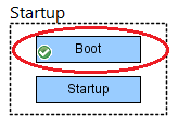
The following shows most SYS/BIOS configuration settings using *.cfg source code snippets. You can also configure 28x applications using the XGCONF Graphical Configuration Tool. For example, when you open the tool, you see the Welcome screen. You can click the System Overview button to see a block diagram of the available SYS/BIOS modules. Modules used by your application have a green checkmark. Notice the modules circled in red in the following figure; they have configuration settings that are specific to 28x devices.
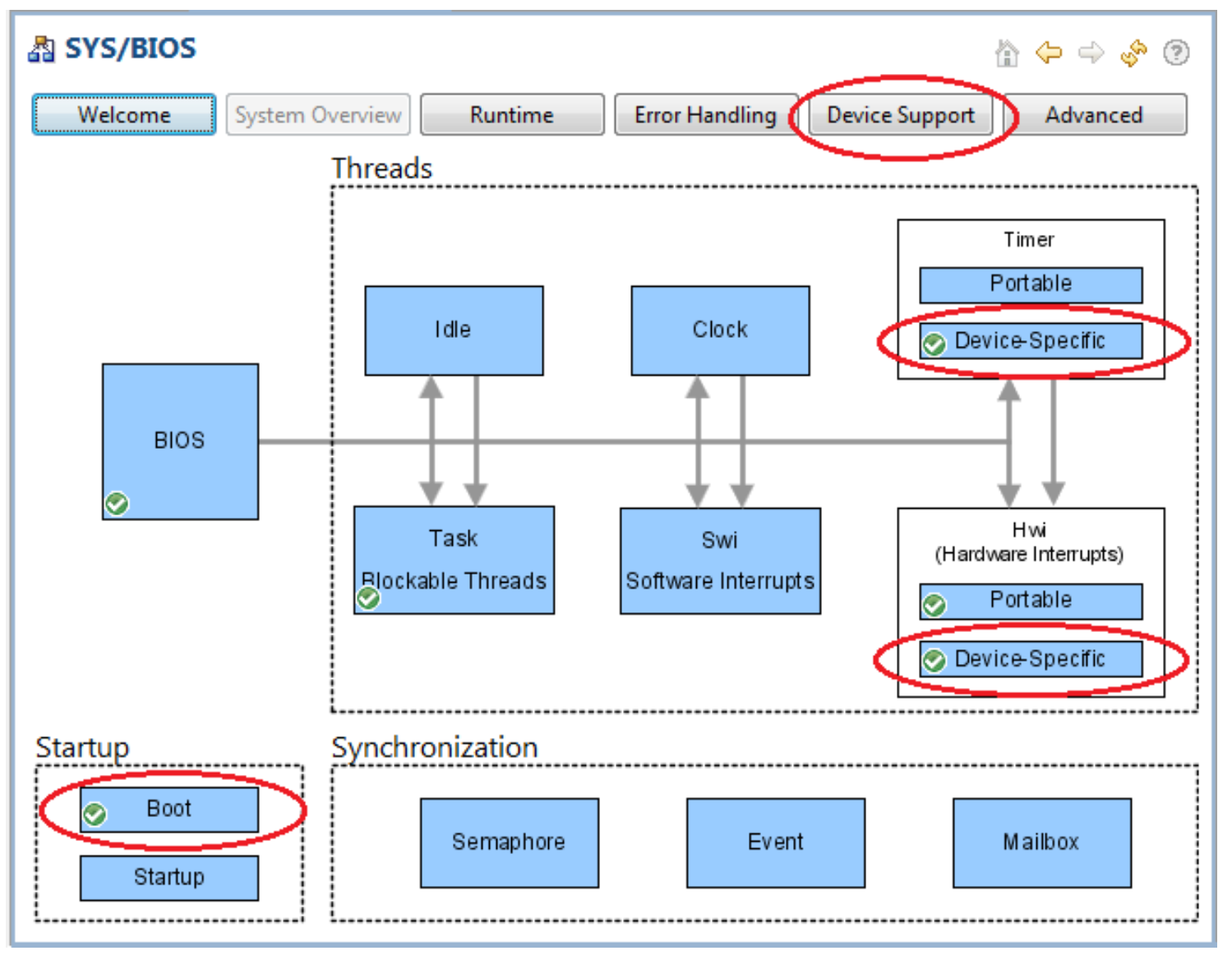
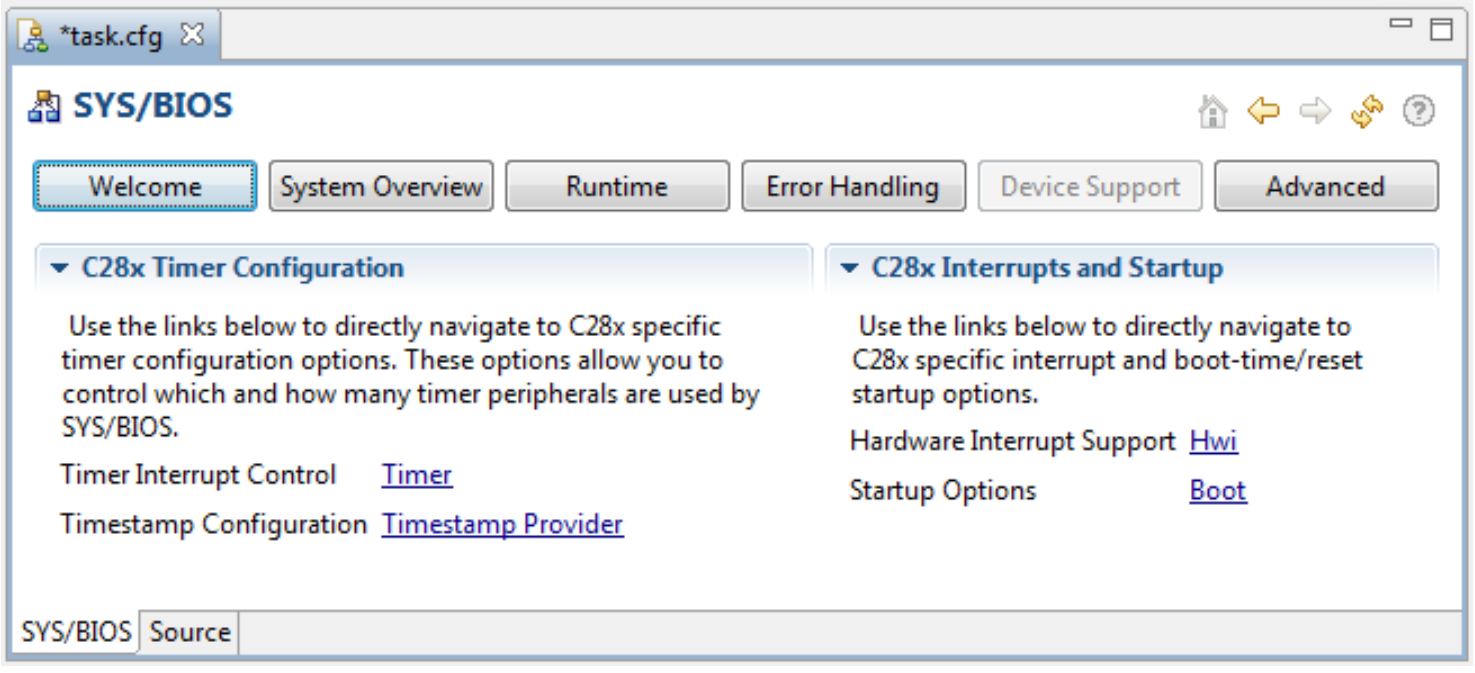
If you click the Device Support button at the top of the XGCONF page, you see a list of SYS/BIOS modules that apply to the 28x. You can click those links to see a configuration page for each module.
Note that some 28x devices do not have enough memory to run SYS/BIOS applications. See the release notes in your SYS/BIOS installation for a detailed, up-to-date list of supported devices.
If you are using a Concerto device, this page describes how to use SYS/BIOS with the 28x part of the Concerto.
First, please look at the general boot for a device with TI-RTOS: https://e2e.ti.com/support/processors/f/791/p/953161/3521880.
For 28x devices, SYS/BIOS installs a configurable Startup reset function called ti_catalog_c2800_init_Boot_init(), which is provided by XDCtools. Depending on your configuration of the ti.catalog.c2800.init.Boot module, this function performs the following actions:
You can configure what the Startup reset function does using the C28x Boot module. First, in XGCONF select the Boot module from the SYS/BIOS System Overview page:
You will see the configuration page for the 28x Boot module.
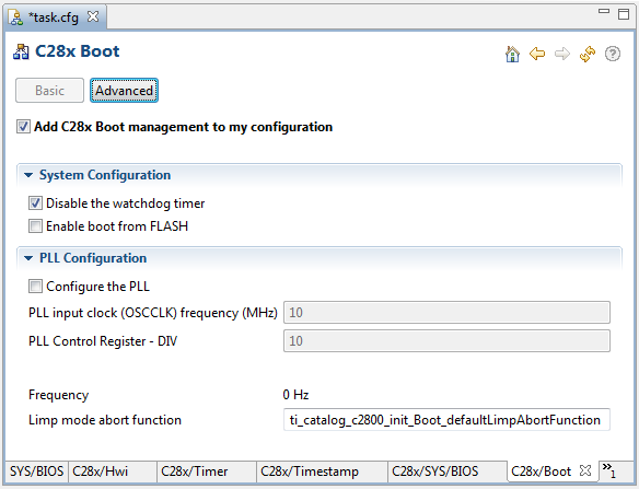
Watchdog timer: By default, the watchdog timer is enabled, meaning that if the system hangs long enough for the watchdog timer's 8-bit counter to reach its maximum value, a system reset is triggered. To prevent this, you can check the "Disable the watchdog timer" box in XGCONF or use the following configuration statements:
var Boot = xdc.useModule('ti.catalog.c2800.init.Boot');
Boot.disableWatchdog = true;
Boot from Flash: If you want to be able to boot this application from Flash, check the "Enable boot from FLASH" box in XGCONF or use the following configuration statements:
var Boot = xdc.useModule('ti.catalog.c2800.init.Boot');
Boot.bootFromFlash = true;
If you configure your application to boot from Flash, a long branch (LB) to the c_int00 entry point will be placed at the BEGIN section address defined in the linker command file.
PLL configuration: The phase-locked loop (PLL) on 28x devices is used to maintain correct clocking rates.
Note: On 280x and 281x devices, XDCtools and SYS/BIOS do not configure the PLL. The PLL is in its default state--bypassed but not turned off--after your application finished booting. If you want to modify the configuration of the PLL on these devices, you can add a Reset function as described at this end of this step (2).
By default, XDCtools automatically enables the PLL for your 2802x, 2803x, 2806x, 282xx, 283xx, or 2834x device. If you want to override the default PLL configuration, you can check the "Configure the PLL" box in XGCONF and set values for the following parameters:
Boot.pllOSCCLK * Boot.pllcrDIV * 1000000) / divider, where divider is 2 if Boot.pllstsDIVSEL is 2 and 4 if Boot.pllstsDIVSEL is 0 or 1.For example, the following configuration statements configure the PLL to a slower rate.
var Boot = xdc.useModule('ti.catalog.c2800.init.Boot');
Boot.configurePll = true;
Boot.pllOSCCLK = 8;
Boot.pllcrDIV = 2;
Boot.pllstsDIVSEL = 0;
User-defined reset functions: If you want to add your own functions to the table of early reset functions, you can do so by adding statements like the following to your application configuration file:
Reset = xdc.useModule('xdc.runtime.Reset');
Reset.fxns[Reset.fxns.length++] = '&myResetFxn';
SYS/BIOS provides the same basic hardware interrupt functionality on 28x devices as it does on other devices. In addition, it provides the ability to configure and use the Peripheral Interrupt Expansion (PIE) block and the zero-latency interrupts supported by 28x devices. The general ti.sysbios.hal.Hwi module is implemented and extended with device-specific functionality by the ti.sysbios.family.c28.Hwi module.
If you want to use only the generic Hwi module run-time APIs and static configuration settings to manage hardware interrupts in your 28x application, you should use the ti.sysbios.hal.Hwi module. To use this module, include the following in your code:
#include <ti/sysbios/hal/Hwi.h>var Hwi = xdc.useModule('ti.sysbios.hal.Hwi');Alternately, you can use the 28x-specific versions of the run-time APIs and static configuration settings provided by the ti.sysbios.family.c28.Hwi module. These include some additional features for 28x only. To use this module, include the following in your code:
#include <ti/sysbios/family/c28/Hwi.h>var Hwi = xdc.useModule('ti.sysbios.family.c28.Hwi');The 28x Peripheral Interrupt Expansion (PIE) block multiplexes numerous interrupt sources into a smaller set of interrupt inputs. The interrupts are grouped into blocks of either eight or sixteen depending on the device and each group is fed into one of 12 CPU interrupt lines (INT1 to INT12). Each of the interrupts is supported by its own vector stored in a dedicated RAM block that serves as a PIE interrupt vector table. The reference guides linked to in the System Control and Interrupts Reference Guides for C28x topic describe the PIE block in more detail.
The vector is automatically fetched by the CPU when servicing the interrupt. It takes nine CPU clock cycles to fetch the vector and save critical CPU registers. Therefore, 28x CPUs can respond quickly to interrupt events. Each individual interrupt can be enabled/disabled within the PIE block.
You use the same Hwi_create() API and Hwi.create() static configuration method to create Hwi objects for the 32 core interrupt lines (INT1 to INT12) and for individual PIE interrupts. Interrupt numbers 0-32 apply to the core interrupt lines (INT1 to INT12), and numbers 32-223 apply to individual PIE interrupts.
The following table shows the mapping between the PIENUM (interrupt ID) and the PIE groups. INTX.Y is the interrupt number for the PIE interrupt belonging to group X and group-specific id Y. For example, in PIE group 2, interrupt 3 would be INT2.3 with an interrupt ID of 42. Note that columns INTX.9-INTX.16 don't apply to all devices; see your device's technical reference manual for more information.
| INTX.1 | INTX.2 | INTX.3 | INTX.4 | INTX.5 | INTX.6 | INTX.7 | INTX.8 | INTX.9 | INTX.10 | INTX.11 | INTX.12 | INTX.13 | INTX.14 | INTX.15 | INTX.16 | |
|---|---|---|---|---|---|---|---|---|---|---|---|---|---|---|---|---|
| INT1.Y | 32 | 33 | 34 | 35 | 36 | 37 | 38 | 39 | 128 | 129 | 130 | 131 | 132 | 133 | 134 | 135 |
| INT2.Y | 40 | 41 | 42 | 43 | 44 | 45 | 46 | 47 | 136 | 137 | 138 | 139 | 140 | 141 | 142 | 143 |
| INT3.Y | 48 | 49 | 50 | 51 | 52 | 53 | 54 | 55 | 144 | 145 | 146 | 147 | 148 | 149 | 150 | 151 |
| INT4.Y | 56 | 57 | 58 | 59 | 60 | 61 | 62 | 63 | 152 | 153 | 154 | 155 | 156 | 157 | 158 | 159 |
| INT5.Y | 64 | 65 | 66 | 67 | 68 | 69 | 70 | 71 | 160 | 161 | 162 | 163 | 164 | 165 | 166 | 167 |
| INT6.Y | 72 | 73 | 74 | 75 | 76 | 77 | 78 | 79 | 168 | 169 | 170 | 171 | 172 | 173 | 174 | 175 |
| INT7.Y | 80 | 81 | 82 | 83 | 84 | 85 | 86 | 87 | 176 | 177 | 178 | 179 | 180 | 181 | 182 | 183 |
| INT8.Y | 88 | 89 | 90 | 91 | 92 | 93 | 94 | 95 | 184 | 185 | 186 | 187 | 188 | 189 | 190 | 191 |
| INT9.Y | 96 | 97 | 98 | 99 | 100 | 101 | 102 | 103 | 192 | 193 | 194 | 195 | 196 | 197 | 198 | 199 |
| INT10.Y | 104 | 105 | 106 | 107 | 108 | 109 | 110 | 111 | 200 | 201 | 202 | 203 | 204 | 205 | 206 | 207 |
| INT11.Y | 112 | 113 | 114 | 115 | 116 | 117 | 118 | 119 | 208 | 209 | 210 | 211 | 212 | 213 | 214 | 215 |
| INT12.Y | 120 | 121 | 122 | 123 | 124 | 125 | 126 | 127 | 216 | 217 | 218 | 219 | 220 | 221 | 222 | 223 |
For example, the following configuration code plugs the function 'myHwi' into the vector table for PIE group 5, interrupt 1. As the above table shows, this corresponds to interrupt ID 64:
var Hwi = xdc.useModule('ti.sysbios.family.c28.Hwi');
/* PIE group 5, interrupt 1 */
var interruptNum = 64;
var hwiParams = new Hwi.Params();
hwiParams.arg = interruptNum;
Hwi.create(interruptNum, "&myHwi", hwiParams);
In addition to creating Hwi objects to service PIE interrupts, you can use the following APIs from the ti.sysbios.family.c28.Hwi module to manage PIE interrupt handling at run-time:
Similar APIs--Hwi_disableIER(), Hwi_enableIER(), and Hwi_restoreIER()--can be used to disable, enable, and restore the core interrupt lines (INT1 to INT12) at run-time.
The Hwi_clearInterrupt() API can be used to clear an interrupt's pending status. For 28x devices this function clears a PIEIFR bit if the interrupt number is a PIE interrupt number. It clears an IFR bit if this is an interrupt number between 1 and 14.
The following additional configuration parameters are provided for configuring 28x interrupts:
You can pass a bitmask to the Hwi.zeroLatencyIERMask property to identify interrupts that should never be disabled. The advantage to doing this is that such interrupts will have minimal interrupt-to-ISR execution time. (Though the property name is named "zero latency", the latency is actually minimized, but not zero.) The disadvantage to using this setting is that when SYS/BIOS disables or enabling interrupts, extra work is required to avoid making changes to such interrupts.
For example, the following configuration code sets INT5 and the PIE group 5 multiplexed to INT5 to provide minimal latency:
var Hwi = xdc.useModule('ti.sysbios.family.c28.Hwi');
Hwi.zeroLatencyIERMask = 0x0010;
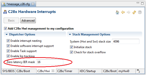
Bit 0 in the IER mask corresponds to INT1 and PIE group 1. Bit 1 corresponds to INT2 and PIE group 2, and so on through INT12. Bits 12-16 are used for other purposes, and should not be set in the zeroLatencyIERMask. In the previous example, a mask of 0x0010 sets bit 4, which corresponds to INT5.
By default, the Hwi.zeroLatencyIERMask property is shown as a decimal value in XGCONF:
Note that all the interrupts in the PIE group whose bit is set in the zeroLatencyIERMask will be treated as zero latency interrupts.
Note: We recommend that you use the zeroLatencyIERMask only if all interrupts in the groups execute non-SYS/BIOS interrupt handlers. This feature is best used only in applications that demand very low latency.
CPU interrupts specified in this mask (which corresponds to the 16-bit IER register) are not disabled by the Hwi_disable() call and are generally left enabled except when explicitly disabled using Hwi_disableIER() or Hwi_disablePIEIER().
If you use zero latency mode for any interrupt, the code used to disable, enable, and restore interrupts in SYS/BIOS will be slower. This is because the code needs to set individual bits in the IER register rather than setting the INTM bit. It is important to be aware of the performance tradeoff associated with using zero latency interrupts before using this feature.
To consolidate code that performs register saving and restoration for each interrupt, SYS/BIOS provides an interrupt dispatcher that automatically performs these actions for an interrupt routine. Use of the Hwi dispatcher allows ISR functions to be written in C. In addition to preserving the interrupted thread's context, the SYS/BIOS Hwi dispatcher orchestrates the following actions:
By default, all Hwi interrupts created statically or dynamically with SYS/BIOS are routed to the interrupt dispatcher.
If you have some interrupts that you do not want serviced by the SYS/BIOS interrupt dispatcher, you should create them using the Hwi_plug() run-time API. Such ISR functions are directly plugged into the vector table. Hwi_plug() can only be used for ISR functions that do not call any SYS/BIOS APIs. If you are using Hwi_plug(), you should also be aware of potential timing and resource access issues between ISRs that are and are not managed by the SYS/BIOS interrupt dispatcher.
If you use Hwi_plug() for any PIE interrupts, your application must clear the CPU acknowledge bit manually for the respective PIE block before further interrupts from that block can occur. The SYS/BIOS interrupt dispatcher normally takes care of this. (This differs from DSP/BIOS 5, in which the application had to acknowledge the interrupt.) If your application contains legacy code with HWI instances created with the legacy-support ti.bios.HWI module, the HWI function must also clear the CPU acknowledge bit manually before returning.
Here is a F28379D example of adding a zero-latency interrupt via Hwi_plug(): /cfs-file/__key/communityserver-discussions-components-files/171/4555.C28_5F00_zero_5F00_latency.pdf
There are two limitations to parameters in the Hwi.Params structure used when you create a Hwi object on 28x devices:
The 28x devices have three 32-bit timers--Timer 0 through Timer 2. By default, SYS/BIOS uses two of these timers, one for the Clock module and one for the Timestamp module. Typically, the timers used by SYS/BIOS are Timer 0 and Timer 1, but if your application uses a timer for its own processing, SYS/BIOS will use Timer 2 if necessary.
You can control which 28x timers used by SYS/BIOS by configuring the ti.sysbios.family.c28.TimestampProvider module. By default, SYS/BIOS uses the first two available timers for the Clock and Timestamp modules. You can specify that the Timestamp module should use, for example, Timer 2 with the following configuration code (in .cfg file):
var TimestampProvider = xdc.useModule('ti.sysbios.family.c28.TimestampProvider');
TimestampProvider.timerId = 2;
The following configuration code causes the Timestamp module to use the same 28x timer as the Clock module:
var TimestampProvider = xdc.useModule('ti.sysbios.family.c28.TimestampProvider');
TimestampProvider.useClockTimer = true;
Sharing the Clock timer leaves more timers available for other uses, but makes the Timestamp APIs less efficient. If you use the Clock timer for timestamps, the timestamp is calculated as: (Clock ticks) x (tick period) + (current timer count) As a result, the maximum value of the timestamp is limited to 2^32 x (Clock tick period).
If you use a separate timer for the timestamp (the default behavior), the maximum value of the timestamp is 2^64 and the multiplication operation is not required in order to retrieve the value.
For Concerto devices, you should use the ti.sysbios.family.[c28|arm].f28m35x.TimestampProvider modules, which access the shared timestamp counter that can be read by either the 28x or M3 core.
Internally, the 28x timers count downward from "period" to 0; however, the Timer_getCount() API subtracts the timer counter value from the period so that it counts upward instead of downward.
The ti.sysbios.family.c28.Timer module configuration lets you specify a mask to identify the CPU timers that are available for use by the Timer module. By default, this mask is set to 7 (111 in binary), which means that Timers 0, 1, and 2 are available. Timers used by SYS/BIOS need not be omitted from this mask, but if your application uses a specific 28x timer, you should omit the bit for that timer from this mask.
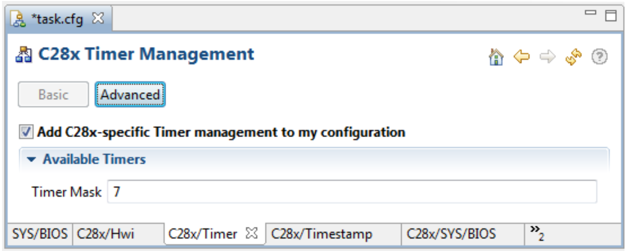
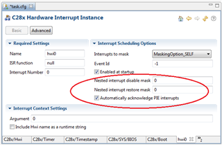
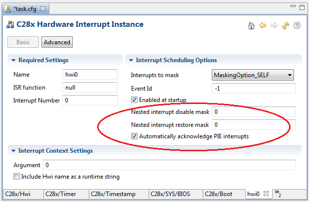
If you create an instance of the device-specific ti.sysbios.family.c28.Timer module (rather than an instance of the generic ti.sysbios.hal.Timer module), you can also configure the 28x parameters circled below:

The Timer Id parameter specifies which 28x CPU timer should be used for this instance. If you choose ANY, the first available timer is used. Remember that 28x devices have 3 timers and SYS/BIOS uses 2 by default.
The Prescale factor parameter sets the length of a timer tick using the 28x device's 16-bit prescaler. If a prescale factor of 10 is specified, a timer tick will occur every 11 cycles. If this timer is used as a counter, the prescale factor determines the period between counts. Otherwise, the prescale factor can be used to achieve longer timer periods; with a prescale specified, the actual period is period * prescale+1
The 28x Timer module provides the following APIs to access the prescaler:
The Free run and Soft stop parameters let you specify how a timer behaves at a software breakpoint, like those you can set in Code Composer Studio. If the "free" flag is set to 1, the timer will continue to run normally when the program halts at a software breakpoint; the value of the "soft" flag doesn't matter if "free" is set to 1. If "free" is 0 and "soft" is 1, the timer will run down to 0 and then stop. When "free" is 0 and "soft" is 0 (the default), the timer halts at software breakpoints.
For example, the following configuration code creates a 28x Timer with a period of 2000 microseconds and a prescale value of 999. As a result, the Timer ticks every 1000 cycles (prescale+1) and the actual period for running the myTimerFxn() function is 2,000,000 microseconds (2 seconds). When a software breakpoint occurs in Code Composer Studio, this Timer will continue to run.
var ti_sysbios_family_c28_Timer = xdc.useModule('ti.sysbios.family.c28.Timer');
var my28xTimerParams = new ti_sysbios_family_c28_Timer.Params();
my28xTimerParams.instance.name = "my28xTimer";
my28xTimerParams.period = 2000;
my28xTimerParams.prescale = 999;
my28xTimerParams.emulationModeInit.free = 1;
my28xTimerParams.emulationModeInit.soft = 0;
Program.global.my28xTimer = ti_sysbios_family_c28_Timer.create(null, "&myTimerFxn", my28xTimerParams);
As with other device-specific Timer modules, you can also specify the creation parameters for the Hwi object to be triggered by this timer interrupt.
Remember that sizes on 28x devices are measured in 16-bit words. The Minimum Addressable Data Unit (MADU) is 16 bits.
Because the amount of memory available on 28x devices is relatively small, reducing the amount of memory used by applications is likely to be important. You may encounter errors when you build an application if the application footprint is too large to fit in RAM. See the "Minimizing the Application Footprint" appendix of the SYS/BIOS User's Guide (SPRUEX3) for a number of ways to reduce the amount of memory used by SYS/BIOS.
Since the 28x RAM is limited, you may want to consider running the application from Flash memory and copying only critical sections to RAM for faster execution.
The System stack and all Task stacks must be located within Page 0 in memory, which has a memory address of 0 to 0xffff. An error is raised if a Task stack is placed in some other memory location. By default, Task stacks are placed in the .ebss:taskStackSection section, which is on Page 0. This section is a subsection of .ebss to allow SYS/BIOS to be used with the CCS-supplied linker .cmd files for the 28x devices.
The .taskStackSection contains the stacks for statically created tasks. The size of the .taskStackSection is calculated as (Task.defaultStackSize * number of static tasks) + system heap size.
To reduce the size of this section, you can do the following:
As you decrease heap and stack sizes, you'll need to watch for "out of memory" errors from heaps and overrunning your stacks. The ROV tool can be helpful in monitoring stack and heap usage.
