This thread has been locked.
If you have a related question, please click the "Ask a related question" button in the top right corner. The newly created question will be automatically linked to this question.
Hello,
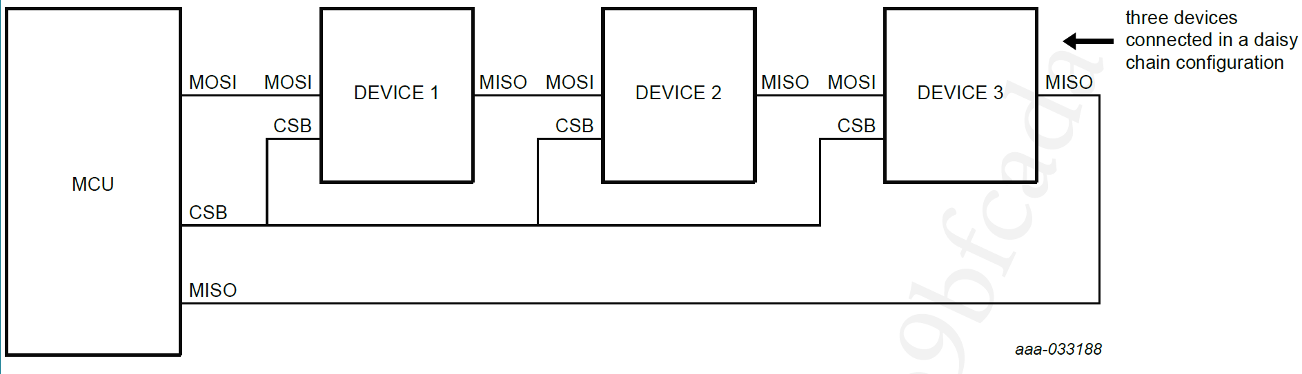
I am using McBSP as SPI master which is connected to 3 SPI slave devices (which are connected in daisy chain fashion).
Each of the slaves require 24-bit data. So I send 72 bit data(24-bit x 3) when I pull the FSX low.
I am updating transmit buffers every 100ms, at the same time I receive the data from the slaves into DRR registers for the time FSX is low and clock is present.
The sequence of device response is device 3 --> device 2 --> device 1.
So the sequence data present in DRR registers should be device 3 --> device 2 --> device 1.
The issue I am facing is i am unable to distinguish what data is present in DRR registers.
My communication clock is set to 500kHz.
McBSP word length: 24 bit
McBSP frame length : 3 words per frame.
I configured the McBSP receive interrupt and I get interrupts only at 100ms, which is period at which i am transmitting.
I checked the RRDY bit. It is set only when i receive all the 3 words. It seems like with my configuration, McBSP treats all the 3 received words are similar.
I need to identify when i receive each word from the slave device.
Any help on this would be appreciated.
Attaching the McBSP Config and SPI slave devices connection.
void init_mcbsp_spi() { // // McBSP-A register settings // // // Reset FS generator, sample rate generator & transmitter // McbspbRegs.SPCR2.all=0x0000; // // Reset Receiver, Right justify word, Digital loopback dis. // McbspbRegs.SPCR1.all=0x0000; // Set McBSP in clock stop mode // McbspbRegs.SPCR1.bit.CLKSTP = 0x2; McbspbRegs.SPCR1.bit.CLKSTP = 0x3; McbspbRegs.PCR.bit.CLKXP = 0x0; McbspbRegs.PCR.bit.CLKRP = 0x1; // // McbspbRegs.PCR.bit.CLKXP = 0x1; // McbspbRegs.PCR.bit.CLKRP = 0x1; McbspbRegs.PCR.bit.CLKXM = 0x1; McbspbRegs.PCR.bit.CLKRM = 0x1; McbspbRegs.PCR.bit.SCLKME = 0x0; McbspbRegs.SRGR2.bit.CLKSM = 0x1; McbspbRegs.PCR.bit.FSXM = 0x1; McbspbRegs.PCR.bit.FSRM = 0x1; McbspbRegs.SRGR2.bit.FSGM = 0x0; McbspbRegs.PCR.bit.FSXP = 0x1; McbspbRegs.PCR.bit.FSRP = 0x1; McbspbRegs.XCR2.bit.XDATDLY=0; McbspbRegs.RCR2.bit.RDATDLY=0; // McbspbRegs.SRGR1.bit.FWID = 0x8F; // McbspbRegs.SRGR2.bit.FPER = 0x47; // McbspbRegs.SRGR1.bit.CLKGDV = 0x5; McbspbRegs.SRGR1.bit.CLKGDV = 0x95; McbspbRegs.RCR1.bit.RWDLEN1 =4; // 24-bit word McbspbRegs.XCR1.bit.XWDLEN1 =4; // 24-bit word McbspbRegs.XCR1.bit.XFRLEN1 = 2; // 3 words per frame McbspbRegs.RCR1.bit.RFRLEN1 = 2; // 3 words per frame //Enable Sample rate generator McbspbRegs.SPCR2.bit.GRST=1; // Enable the sample rate generator delay_loop(); // Wait at least 2 SRG clock cycles McbspbRegs.SPCR2.bit.XRST=1; // Release TX from Reset McbspbRegs.SPCR1.bit.RRST=1; // Release RX from Reset McbspbRegs.SPCR2.bit.FRST=1; // Frame Sync Generator reset // // // // // (CLKXM=CLKRM=FSXM=FSRM= 1, FSXP = 1) // // // McbspbRegs.PCR.all=0x0F08; // // McbspbRegs.SPCR1.bit.DLB = 0; // // // // // Together with CLKXP/CLKRP determines clocking scheme // // // McbspbRegs.SPCR1.bit.CLKSTP = 2; // // McbspbRegs.PCR.bit.CLKXP = 0; // CPOL = 0, CPHA = 0 rising edge no delay // McbspbRegs.PCR.bit.CLKRP = 0; // // // // // FSX setup time 1 in master mode. 0 for slave mode (Receive) // // // McbspbRegs.RCR2.bit.RDATDLY=01; // // // // // FSX setup time 1 in master mode. 0 for slave mode (Transmit) // // // McbspbRegs.XCR2.bit.XDATDLY=01; // // // McbspbRegs.SRGR2.all=0x2000; // CLKSM=1, FPER = 1 CLKG periods // McbspbRegs.SRGR1.all= 0x000F; // Frame Width = 1 CLKG period, CLKGDV=16 // // McbspbRegs.SPCR2.bit.GRST=1; // Enable the sample rate generator // delay_loop(); // Wait at least 2 SRG clock cycles // McbspbRegs.SPCR2.bit.XRST=1; // Release TX from Reset // McbspbRegs.SPCR1.bit.RRST=1; // Release RX from Reset // McbspbRegs.SPCR2.bit.FRST=1; // Frame Sync Generator reset }
Hi Abhinand,
Please note the highlighted portion of Table 12-14. Bits Used to Enable and Configure the Clock Stop Mode within the Technical Reference Manual for F28335.
The design for McBSP in SPI mode calls for a transmit and receive frame length of 1. While you may see that it is working sometimes under other values, we cannot guarantee that the design will operate properly under all conditions.
Having a frame length of 1 will change the behavior of your McBSP FSX signal. I would suggest that instead you use a manually controlled GPIO which toggles at the proper time.
After doing the above, RRDY should then be set to 1 every time you receive a serial word.
Best Regards,
Marlyn