This thread has been locked.

If you have a related question, please click the "Ask a related question" button in the top right corner. The newly created question will be automatically linked to this question.

Compiler/DRV8312-C2-KIT: DRV8312-C2-KIT with MatLab 2019a, CCS 6.2 & UniFlash 4.1

Part Number: DRV8312-C2-KIT
Other Parts Discussed in Thread: UNIFLASH, MOTORWARE, TMS320F28035, LAUNCHXL-F28069M, CONTROLSUITE, DRV8312, INSTASPIN-BLDC

Tool/software: TI C/C++ Compiler

Hello,

we have a DRV8312-69M-KIT (2019) and for that we have installed and configured to work properly, MatLab 2019a, CCS 6.2 and UniFlash 4.1. Taking the example c28069pmsmfoc_ert.slx and building (compiling), it is generating a c28069pmsmfoc_ert.out, which is loaded easily in DRV8312-69M-KIT by using UniFlash 4.1 app. Also, it is possible to compile any Lab project given in MotorWare app by using CCS 6.2

Last month (Nov. 2020) we have bought a DRV8312-C2-KIT and we have tried to put it working with the same software (MatLab 2019a, etc.) but it is impossible. We have downloaded the new version of TI C2000 Piccolo Support from Embedded Coder and also Concerto version, but we have not found c28035pmsmfoc_ert.slx in this package. Where is the examples for DRV8312-C2-KIT?

On the other hand, we have compiled a simple Simulink diagram with Digital Output for 28035 and it can not loaded in DRV8312-C2-KIT by using UniFlash 4.1, while the same version for  28069 loads properly. It seems that the problem is due to the USB (JTAG) interface. For 28069 UniFlash uses XDS 100 v2 and for 28035 it is not valid, being valid XDS 100 v1 (according to TI web, DRV8312-C2-KIT info). The problem is that UniFlash 4.1 does not support XDS 100 v1, neither UniFlash 6.1. Perhaps the solution could be to configure v2 as v1, if somebody knows how to do?

Then, please, somebody could help me saying how versions of MatLab, TI C2000 Support, CCS and UniFlash are neccesary to work easily for DRV8312-C2-KIT and DRV8312-69M-KIT at the same time.

Thank you very much!

Patxi

  • You might implement the latest versions of the CCS and uniflash tool as the link below that can support all of the C2000 devices includes the tools you mentioned above. 

    https://www.ti.com/microcontrollers/c2000-real-time-control-mcus/design-development.html#software

    Please refer to the following link about Matlab for C2000.

    [FAQ] Sticky: MathWorks Solutions for C2000 MCU’se2e.ti.com/.../484814

  • Hello,

    we have reinstalled TI C2000 Piccolo Support from Embedded Coder, and finally we have compiled c28035pmsmfoc_ert.slx project correctly by using CCS 6.2

    But on the other hand, we can not put working DRV8312-C2-KIT . When the Kit is connected to the computer, Windows 10 detects it as a 'Texas Instruments XDS100´+RS232 V1.0" device. The problem is when we are triying to connect with the Kit, it is impossible. We have tried by using CCS 6.2 and the Target Configuration tool/window with 'Texas Instruments XDS100v1 Debug Probe' and different boards all with  28035 (Developer's Kit Dual Motor Contro and PFC, and also, Motor Control and PFC, Experimenter's Kit Piccolo F28035, TMS320F28035), and always the same error is appearing (see below). Also, we have updated this CCS 6.2 and installed the last version, that is CCS 10.1.1

    To quit doubts, we have changed the USB cable and the results are the same. Moreover, we have taken the Control Card 69M which is plugged in our DRV8312-69M-KIT (2019) and replacing by the 28035, we have seen that the motherboard (with its motor) is working fine without any problem. Then, we we have concluded that the fail is in Control Card 28035.

    We have lost several days with this issue and we wish to use our new Kit next month with our students, but it is not any problem if this Kit is based on the Control Card 69M. Could somebody contact me please?

    Thank you very much,

    Patxi

    Target Configuration tool/window Testing result:

    [Start: Texas Instruments XDS100v1 USB Debug Probe_0]

    Execute the command:

    %ccs_base%/common/uscif/dbgjtag -f %boarddatafile% -rv -o -F inform,logfile=yes -S pathlength -S integrity

    [Result]


    -----[Print the board config pathname(s)]------------------------------------

    C:\Users\ispalegp\AppData\Local\TEXASI~1\
        CCS\ti\0\0\BrdDat\testBoard.dat

    -----[Print the reset-command software log-file]-----------------------------

    This utility has selected a 100- or 510-class product.
    This utility will load the adapter 'jioserdesusb.dll'.
    The library build date was 'May 30 2018'.
    The library build time was '23:03:35'.
    The library package version is '8.0.27.9'.
    The library component version is '35.35.0.0'.
    The controller does not use a programmable FPGA.
    The controller has a version number of '4' (0x00000004).
    The controller has an insertion length of '0' (0x00000000).
    This utility will attempt to reset the controller.
    This utility has successfully reset the controller.

    -----[Print the reset-command hardware log-file]-----------------------------

    The scan-path will be reset by toggling the JTAG TRST signal.
    The controller is the FTDI FT2232 with USB interface.
    The link from controller to target is direct (without cable).
    The software is configured for FTDI FT2232 features.
    The controller cannot monitor the value on the EMU[0] pin.
    The controller cannot monitor the value on the EMU[1] pin.
    The controller cannot control the timing on output pins.
    The controller cannot control the timing on input pins.
    The scan-path link-delay has been set to exactly '0' (0x0000).

    -----[The log-file for the JTAG TCLK output generated from the PLL]----------

    There is no hardware for programming the JTAG TCLK frequency.

    -----[Measure the source and frequency of the final JTAG TCLKR input]--------

    There is no hardware for measuring the JTAG TCLK frequency.

    -----[Perform the standard path-length test on the JTAG IR and DR]-----------

    This path-length test uses blocks of 64 32-bit words.

    The test for the JTAG IR instruction path-length failed.
    The JTAG IR instruction scan-path is stuck-at-ones.

    The test for the JTAG DR bypass path-length failed.
    The JTAG DR bypass scan-path is stuck-at-ones.

    -----[Perform the Integrity scan-test on the JTAG IR]------------------------

    This test will use blocks of 64 32-bit words.
    This test will be applied just once.

    Do a test using 0xFFFFFFFF.
    Scan tests: 1, skipped: 0, failed: 0
    Do a test using 0x00000000.
    Test 2 Word 0: scanned out 0x00000000 and scanned in 0xFFFFFFFF.
    Test 2 Word 1: scanned out 0x00000000 and scanned in 0xFFFFFFFF.
    Test 2 Word 2: scanned out 0x00000000 and scanned in 0xFFFFFFFF.
    Test 2 Word 3: scanned out 0x00000000 and scanned in 0xFFFFFFFF.
    Test 2 Word 4: scanned out 0x00000000 and scanned in 0xFFFFFFFF.
    Test 2 Word 5: scanned out 0x00000000 and scanned in 0xFFFFFFFF.
    Test 2 Word 6: scanned out 0x00000000 and scanned in 0xFFFFFFFF.
    Test 2 Word 7: scanned out 0x00000000 and scanned in 0xFFFFFFFF.
    The details of the first 8 errors have been provided.
    The utility will now report only the count of failed tests.
    Scan tests: 2, skipped: 0, failed: 1
    Do a test using 0xFE03E0E2.
    Scan tests: 3, skipped: 0, failed: 2
    Do a test using 0x01FC1F1D.
    Scan tests: 4, skipped: 0, failed: 3
    Do a test using 0x5533CCAA.
    Scan tests: 5, skipped: 0, failed: 4
    Do a test using 0xAACC3355.
    Scan tests: 6, skipped: 0, failed: 5
    Some of the values were corrupted - 83.3 percent.

    The JTAG IR Integrity scan-test has failed.

    -----[Perform the Integrity scan-test on the JTAG DR]------------------------

    This test will use blocks of 64 32-bit words.
    This test will be applied just once.

    Do a test using 0xFFFFFFFF.
    Scan tests: 1, skipped: 0, failed: 0
    Do a test using 0x00000000.
    Test 2 Word 0: scanned out 0x00000000 and scanned in 0xFFFFFFFF.
    Test 2 Word 1: scanned out 0x00000000 and scanned in 0xFFFFFFFF.
    Test 2 Word 2: scanned out 0x00000000 and scanned in 0xFFFFFFFF.
    Test 2 Word 3: scanned out 0x00000000 and scanned in 0xFFFFFFFF.
    Test 2 Word 4: scanned out 0x00000000 and scanned in 0xFFFFFFFF.
    Test 2 Word 5: scanned out 0x00000000 and scanned in 0xFFFFFFFF.
    Test 2 Word 6: scanned out 0x00000000 and scanned in 0xFFFFFFFF.
    Test 2 Word 7: scanned out 0x00000000 and scanned in 0xFFFFFFFF.
    The details of the first 8 errors have been provided.
    The utility will now report only the count of failed tests.
    Scan tests: 2, skipped: 0, failed: 1
    Do a test using 0xFE03E0E2.
    Scan tests: 3, skipped: 0, failed: 2
    Do a test using 0x01FC1F1D.
    Scan tests: 4, skipped: 0, failed: 3
    Do a test using 0x5533CCAA.
    Scan tests: 5, skipped: 0, failed: 4
    Do a test using 0xAACC3355.
    Scan tests: 6, skipped: 0, failed: 5
    Some of the values were corrupted - 83.3 percent.

    The JTAG DR Integrity scan-test has failed.

    [End: Texas Instruments XDS100v1 USB Debug Probe_0]

  • It seems like the on-board emulator doesn't work well, please check if the switch (SW3) is set to "ON", and take a look at the links below.

    [FAQ] Sticky: Enable XDS100 USB Serial Port on LAUNCHXL-F28069M

    https://e2e.ti.com/support/microcontrollers/c2000/f/171/t/670519>

    http://software-dl.ti.com/ccs/esd/documents/ccsv7_debugging_jtag_connectivity_issues.html

  • Hello Yaming Luo,

    thank you for your answer, but I can not put it running: (1) The SW3 is in on position (UP) but it is not connectig properly with LauntchXLF28069M  and (2) the device is detected correctly by my Windows 10.

    As previously I commented (last day), we have not any problem if the 28035 Control Card is replaced by the 28069M Control Card, because the motherboard (main board) is working properly. Then, clearly the 28035 Control Card is failing. I would like to find a practical solution because we need it working next month by using with our students, i.e., you could send us a 28069M Control Card for this Kit and after we can give back the 28035 Control Card: we bought to you in 5th November 2020 the EVM8312-C2-KIT (Order T00992726).

    Thanks,

    Patxi Alkorta Egiguren

    (2)

    (1)

  • Sorry. We can't provide such a service to send the F28069M controlCard instead of the F28035 one even though the F28035 is not workable. You have to order a new F28069M controlCard if you want this.

    And could you please post a picture to show what F28035 controlCard you are using? The DRV8312 kit can support all of the C2000 controlCards. Did you try to use an example of F28035 in controlSUITE to test the controlCard?

  • Hi Yanming Luo,

    as you can understand, I'm very unsatisfy due that we have payed 306 € for this Kit thinking that it is so easy to program as based in F28069M, and after several day we can not put it working. We have settled the knowledge to compile and program, as you can see our videos in https://ehubox.ehu.eus/apps/files/?dir=/DRV8312&fileid=95491853 for ti_software@list.ti.com.

    It is clear that the solution for us is a F28069M Control card, but with InstaSpinFOC/MOTION routines, that is, which is used as Control card of DRV8312-69M-KIT and others. Could you send us or indicate the link of this reference in you web, please?

    These two days the school is closed and on thursday we can try to probe an example of ControlSUITE.

    Regarding the pictures, here there are two of them.

    Regards,

    Patxi

  • Did this F28035 controlCard work well using the on-board emulator if you use an example for F28035 in controlSUITE, not use your own project?

    Do you mean that you want to run the instaSPIN-FOC/Motion on this DRV8312-kit? You have to use the F28069M controlCard, only some of C2000 devices support the instaSPIN-FOC or InstaSPIN-Motion, please find the related devices that supports InstaSPIN-FOC, or IntsaSPIN-Motion as the links below.

    View InstaSPIN-MOTION enabled MCUs

    http://www.ti.com/microcontrollers/c2000-real-time-control-mcus/products.html#p2192=InstaSPIN-MOTION%20Technology 

    View InstaSPIN-FOC enabled MCUs 

    http://www.ti.com/microcontrollers/c2000-real-time-control-mcus/products.html#p2192=InstaSPIN-FOC%20Technology

    Download motorware which has many example projects to support this kit, and follow the lab guide to understand these lab projects.

    http://www.ti.com/tool/motorware

  • Hi Yanming Luo,

    thanks for the information: finally we can see that the Control card with InstaSpin routines is the TMDSCNCD28069MISO. Anyway, the Control card which is on the DRV8312-C2-KIT is also provided with this InstaSpin routines.

    www.ti.com/.../DRV8312-C2-KIT

    On the other hand, we have tried to test the following example of controlSUITE: F2803x Flashing LEDs Project. It has been copied to the Workspace of CCS 6.2 (Code Composer Studio) and compiled without any problem. But, when we have tried to connect and load the example to the Kit (28035), it is giving the Debug problem (see next figure, below). Triying to solve reviewing and repeating the Target Configuration tool process (as done in 23th December, above), it has the same communication problem.

    Sincerely, we are ready to do more tests in order to solve this problem and to start working with our new Kit. A simple example that you can do there with CCS 6.2 and this Control card (28035) which works properly, we could repeat here without any problem.

    Thank you very much.

    Patxi

  • As mentioned above, please follow the instructions in the following link to connect the emulator, make sure that the switch (SW3) is set to "ON" on the controlCard. The link can be used for F28035 controlCard also.

    https://e2e.ti.com/support/microcontrollers/c2000/f/171/t/670519>

    http://software-dl.ti.com/ccs/esd/documents/ccsv7_debugging_jtag_connectivity_issues.html

    There are many examples in controlSUITE can be used for F28035, even it includes some motor control example project based on F28035. Make sure that the target configuration is set correctly for F28035 controlCard with the XDS100 emulator if you are using the F28035 example in controlSUITE.

  • Dear Yanming Luo,

    finally the problem was solved.

    Thank you very much for your support!

    Patxi

    The following lines explain the solution process, for someboy was interested:

    Initially the ControlCard28035 was reprogrammed by using MProg.exe, as you recommended, but I could not program the chip with our programs.

    Then, seeing in the 6th page of the document InstaSPIN-BLDC Sensorless Control.pdf it is clear that the correct position to program this control card is (ON) is DOWN, and not UP as in lots of forum’s threads is commented. (c:\ti\controlSUITE\development_kits\DRV8312-C2-KIT_v128\InstaSPIN_BLDC\~Doc\)

    After change the position of SW3 to ON (DOWN), it can be programmed as the user wish (by using CCS, MatLab/Simulink, UniFlash).

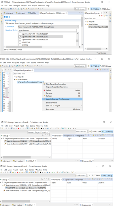
    Anyway, by using CCS the error of Target Configuration tool/window Testing (Test result) is keeping the same. But there is a way to get it without any problem (in spite of some error message appear). The idea of the solution was extracted from this video on You Tube (between 4th and 7th minutes) https://www.youtube.com/watch?v=M9XWL4NDtnU and the following screens explain how to load in the Flash memory a simple program (prueba28035.slx) compiled in MatLab 2019a/Simulink (flashing Led2 at 0.5 s and Led 3 at 0.1 s of period), by using CCS 6.2.0. The compilation gives prueba28035.out file and i was employed as an example:

    C28xx: Error: (Error -150 @ 0x0) One of the FTDI driver functions used during configuration returned a invalid status or an error. (Emulation package 8.0.27.9). C28xx: Unable to determine target status after 20 attempts .C28xx: Failed to remove the debug state from the target before disconnecting. There may still be breakpoint op-codes embedded in program memory. It is recommended that you reset the emulator before you connect and reload your program before you continue debugging

    In spite of these errors, it is possible to use debugger. The following figure shows the speed reference value (a ramp from 0 to 15) applied to the motor (based in c28035pmsmfoc_ert.slx example of Simulink, which was compiled with Simulink and after programmed by using CCS), in which there is not any error.