This thread has been locked.

If you have a related question, please click the "Ask a related question" button in the top right corner. The newly created question will be automatically linked to this question.

CCS/TMS320F28386D: CM-I2C occassionally put "NACK" while doing "Master Multi-byte Read"

Part Number: TMS320F28386D

Tool/software: Code Composer Studio

Hi, there.

I met a problem when executing code ReadMultiBytesWithStartAddr() like the attached one :I2C_ReadTest.zip

Sometimes it just worked fine, but sometimes it received data and put a "NACK". After logic analysis, it is inspected that some byte seems to "lack a clock pulse" probably as shown below :

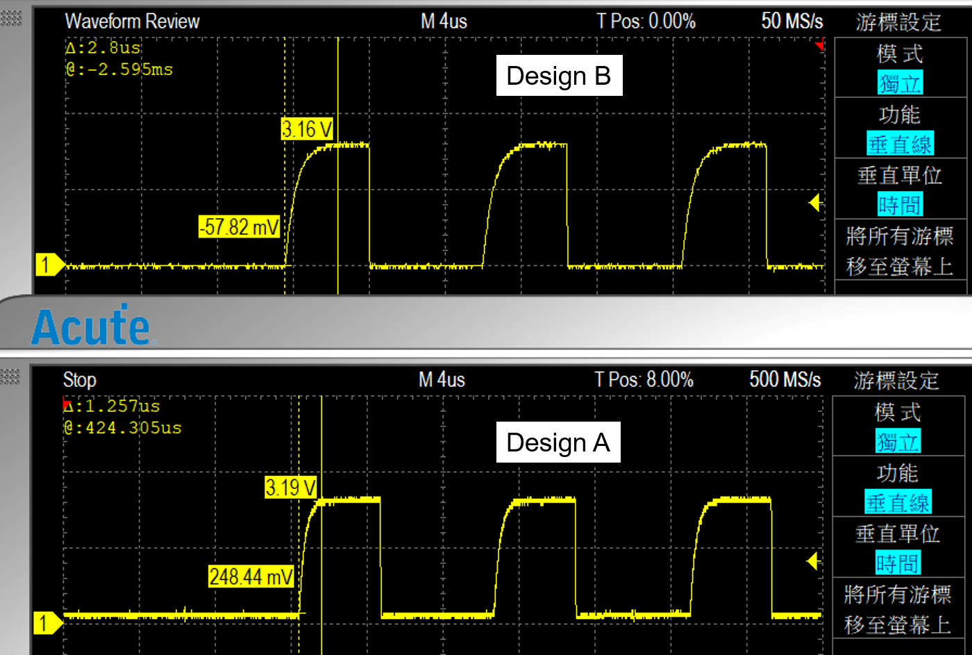
In normal situation, you will see like :

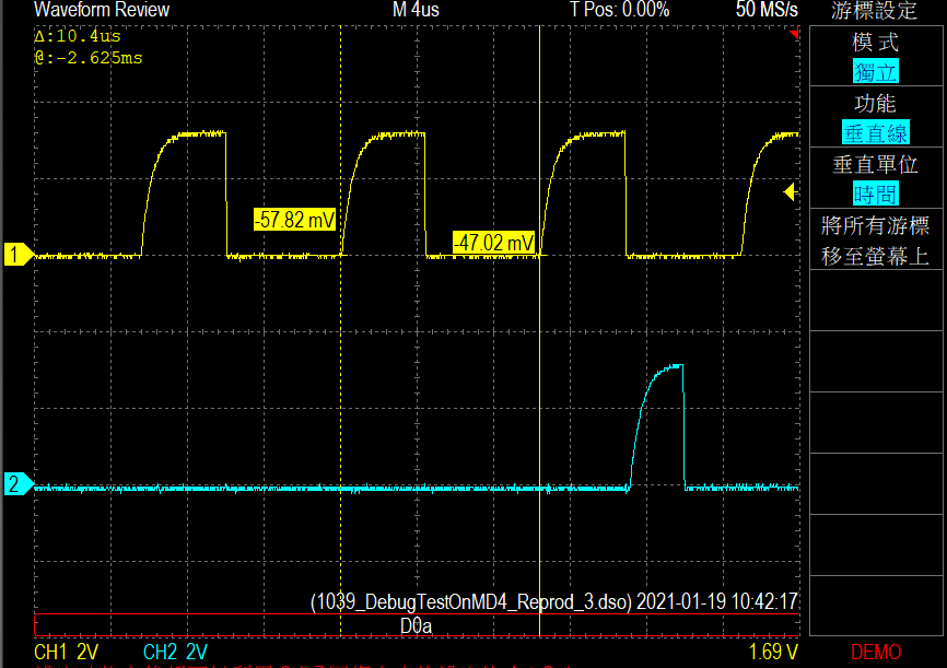
When it works abnormally, you will see like :

Why's that? Did you have any suggestion?

Thanks.

  • When this condition occurs, what do the status registers say? Can you capture the I2CMCS register?

    Whitney

  • Following my example code, software thought the whole process is finished, which means that it couldn't see any error status like ADRACK or DATACK....etc.

    Today I found another strange problem. CM-I2C module occassionally lack a clock like the picture below:

    I guess it seems to get into the same situation like the original problem I posted. But this time, it made EEPROM chip stuck and software thought the whole process ran out.

  • Henry,

    It would be possible that you might have wrong pull-up resistor for the I2C bus speed you are working?

    How strong is your pull-up resistor? What is your I2C bus capacitance? What is the I2C bus speed?

    Regards,

    Manoj

  • Manoj,

    Thanks for advice first. Our circuit design worked fine on I2CA module in CPU1, and its speed maintains 100 KHz as working on I2CA module.

    Is the resistor or capacitor not compatible for CM-I2C but I2CA module? Why does only few clocks miss?

  • Henry,

    I2CA found in C28x core is a different design compared to CM-I2C found in connectivity manager.C28x-I2CA working on the same board doesn't guarantee CM-I2C working because of difference in design.

    Based on my experience handling different I2C questions over the last 2 years, I found many cases where unexpected NACK problem goes away by changing pull-up resistors, modifying bus capacitance and adding series resistors etc. General rule of thumb, having a stronger pull-up resistors typically around 1Kohms - 2 Kohms is good than having weaker pull-up resistor. That is the reason why I raised those questions.

    Regards,

    Manoj

  • Manoj,

    FYI, our pull-up resistor is 3.3 Kohm. Does this explain the condition I faced? I'm curious about why only few clocks make this happen?

  • Henry,

    3.3k Pull-up resistor looks okay.

    Ninth SD-Cx clock pulse in your oscilloscope picture looks like noise glitch. This is possibly affecting the I2C state machine. I woutd think finding ways to remove noisy glitch to get over the issue.

    With pull-up resistor looking good, I would try adding series resistors (around 20 - 30 ohms) and 50pf on SCL / SDA lines.This should eliminate noisy glitches.

    Regards,

    Manoj

  • Manoj,

    According to your noisy glitch guessing, I tried to set glitch suppression (I2CMTPR, PULSEL) from 1 clock to 8 clocks. Fortunately, it works! I'll test it for a long run.

    Anyway, thanks for reminder.

  • Henry Teng said:

    Manoj,

    According to your noisy glitch guessing, I tried to set glitch suppression (I2CMTPR, PULSEL) from 1 clock to 8 clocks. Fortunately, it works! I'll test it for a long run.

    Anyway, thanks for reminder.

    I have tested 3 levels: 8 clocks, 16 clocks, 31 clocks. Only 8 clocks should work fine. I still have questions about it.

    CM system clock is 125 MHz and our applied SCL speed is 100 KHz. Even glitch suppression setting at 31 clocks, which means noise frequency higher than 4 MHz might be suppressed. And the bandwidth still 4x times higher than 100 KHz.

    Why did "SCL pulses missing" happen again at 16 and 31 clocks levels of glitch suppression setting?

  • Henry,

    I need to check with design team on the glitch filter behavior.This turn around time would take atleast 5 - 7 working days to get back with you.

    Based on your observation, 8 CMCLK (I2CMTPR.PULSEL = 5) works fine without any issues. But, 16 clocks (or) 31 clocks don't work at. Correct?

    Have you already made sure SCL clock frequency is indeed 100 KHz?

    Can you share your SCL / SDA scope shots?

  • Manoj,

    With CM system clock 125 MHz, SCL speed is about 95 KHz, not exactly 100 KHz, as you can see.

    I'm pretty sure that the register set is right with example interface like:

    I2C_initMaster( I2C0_BASE, I2C_CLK_FREQ, false );

    Another thing, if I set glitch suppression like:

    I2C_configureMasterGlitchFilter( I2C0_BASE, I2C_MASTER_GLITCH_FILTER_16 );

    or

    I2C_configureMasterGlitchFilter( I2C0_BASE, I2C_MASTER_GLITCH_FILTER_31 );

    Sometimes it reproduce the condition like the previous observation (the spike about 400 ns). The condition of clock missing is not fixed at certain step in program. It occurred uncertainly.

    Hope these messages useful, and thanks for forwarding message.

  • Henry,

    With CMCLK running at 125 MHz,

    PULSEL  = 5 (8 clocks) would be able to gobble noise glitches less than (8 / 125 MHz)  =  64 ns

    PULSEL =  6 (16 clocks) would be able to gobble noise glitches less than (16 / 125 MHz) = 128 ns

    PULSEL =  7 (31 clocks) would be able to gobble noise glitches less than (31 / 125 MHz) = 248 ns.

    In your case your noise gliches is around 400ns which almost twice what software noise filter could gobble. So, none of these configurations would help consistently. You need to supplement with ferrite beads, series resistor and additional bus capacitance. Adding additional bus capacitance might also require you to reduce size of pull-resistors to say 1k (or) 2k

    Regards,

    Manoj

  • Manoj Santha Mohan said:

    In your case your noise gliches is around 400ns which almost twice what software noise filter could gobble. So, none of these configurations would help consistently. You need to supplement with ferrite beads, series resistor and additional bus capacitance. Adding additional bus capacitance might also require you to reduce size of pull-resistors to say 1k (or) 2k

    Hi, Manoj.

    I don't agree that spike came from other devices. After that spike missed, you can see the SCL held low for a certain period just like other normal pulses in the later duty. On the other hand, probably CM-I2C drained that bus for 400 ns and release it. Even the rising time of that signal is familiar to the normal pulses if you watch it in detail.

  • Henry,

    I never said spike is coming from other devices either. It could be board / cable artifact caused by EMI noise, cross coupling, switching noise, ground-bouncing etc are possible reasons for noise.

    Are you suspecting the CM-I2C is generating the noise glitch?

    Regards,

    Manoj

  • Hi, Manoj.

    Understood. I’ll try attaching capacitor on I2C bus.

    Regarding of those explanation, shall me conclude this condition might be caused  by noise rather than misusing registers?

  • Hi Henry,

    Are there any slow devices trying to stretch the clock. Can you run at a lower clock rate to test?

    Thanks,

    Joe

  • Henry,

    With PULSEL > 5, it satisfies I2C specification with CMCLK running at 125 MHz. So, I don't think your register configuration is the reason. Your noise glitches are around 400ns which is much greater than what software filter could gobble. You need to find ways to reduce the noises glitches by adding series termination resistors and / or increasing bus capacitor.

    PULSEL  = 5 (8 clocks) would be able to gobble noise glitches less than (8 / 125 MHz)  =  64 ns

    PULSEL =  6 (16 clocks) would be able to gobble noise glitches less than (16 / 125 MHz) = 128 ns

    PULSEL =  7 (31 clocks) would be able to gobble noise glitches less than (31 / 125 MHz) = 248 ns.

    Regards,

    Manoj

  • Joe Josn2 said:

    Hi Henry,

    Are there any slow devices trying to stretch the clock. Can you run at a lower clock rate to test?

    Thanks,

    Joe

    The whole communication process in our design system worked fine with CPU I2CA module. That is, we just transplant the bottom module from I2CA module to CM-I2C0 module. Your guess may not be one of causes in my opinion.
    In addition, I2C clock rate still remains about 100 KHz. Although the CM system clock is recommended to set as 125 MHz, the I2C clock frequency is set at 95 ~ 100 KHz actually, which is a little bit slower than the original one from I2CA module.

    Thanks for you advice anyway.

  • Manoj Santha Mohan said:

    Henry,

    With PULSEL > 5, it satisfies I2C specification with CMCLK running at 125 MHz. So, I don't think your register configuration is the reason. Your noise glitches are around 400ns which is much greater than what software filter could gobble. You need to find ways to reduce the noises glitches by adding series termination resistors and / or increasing bus capacitor.

    PULSEL  = 5 (8 clocks) would be able to gobble noise glitches less than (8 / 125 MHz)  =  64 ns

    PULSEL =  6 (16 clocks) would be able to gobble noise glitches less than (16 / 125 MHz) = 128 ns

    PULSEL =  7 (31 clocks) would be able to gobble noise glitches less than (31 / 125 MHz) = 248 ns.

    Regards,

    Manoj

    Hi, Manoj.

    I got news with your suggestion. "Clock missing" still happened when we changed our pull-up resistor into 1.6 kohm. Suggestion with capacitor serial-connection has not been tested yet. In my arrogant opinion, if it is actually caused by EMI noises, capacitor serial-connection might be not helping.

    I observed I2C bus with another circuit design (later called design A) which never happened that condition which means "clock missing". The rising time of pulses seems to be less than the circuit (later called design B) which usually happened that condition.

    May this condition be the key of "clock missing"? Does TI guarantee that CM-I2C module shall work fine with the certain rising time of SCL pulses?

    Thanks.

  • Henry,

    Design A (with 1.6 Kohm pull resistor) has faster rise time compared to Design B (with 3.3 Kohm pull resistor). This behavior is expected because a stronger pull-up will charge the bus capacitor faster. It however doesn't help with reducing noise. That can be only achieved with including ferrite beads, series resistor and increasing bus capacitor which acts as low pass filter. When you increase your bus capacitance, you generally need to have a stronger pull-up to have faster rise time.

    I would try series termination resistor 33 ohms and bus capacitance of say 50pF and see whether problem goes away. If not you may need to try playing around with different combination of series resistor / bus capacitance.

    Rs1, RS2 are the series termination resistors. These series resistor has to be placed as close as possible to device pins.

    Cp is the bus capacitance

    Regards,

    Manoj