This thread has been locked.
If you have a related question, please click the "Ask a related question" button in the top right corner. The newly created question will be automatically linked to this question.
Hi,
I'm relatively new to TI products. I have previously worked with a TMS320f280049 and now I was looking into the f28377x due to its increased flash memory.
I have a LaunchXL-F28377S and I'm trying to build software which I know it's around 700KB, although this is failing due to lack of space for my .econst which is being allocated to the flash in the linker file as intended.
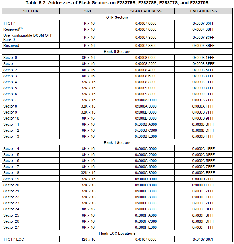
My main question is, where in the linker file is the info about the Flash memory? I can see
FLASHA_N : origin = 0x080002, length = 0x03FFFE /* on-chip Flash */
This length translates to 262142, does it mean it's only 262KB? (where's the rest? it's supposed to be 1024KB right?) The datasheet also says it should have 2 banks but I can only see one on c28377S.cmd
I can build when I assign .econst to EMIF1_CS0_MEMORY but in all honesty I have no idea what I'm doing when doing this so if you have any hints on how to get a better grasp on how much memory I need and how much memory I have available this would be most appreciated.
I will keep trying stuff but at the moment I'm a bit clueless so I'm opening this thread to hopefully get some clarity shortly reduce my trial in error attempts.
PS: I could not find the right part number so I chose the closest one, the right one is in the title.
Many thanks.
Celso
Celso,
Part of the initiation to C28x is being confused about data sizes. The C28x core has a minimum addressable word size of 16-bits, as opposed to the more common 8-bit addressability. So when the datasheet says that there is 1-MB of flash, it means 1-M x 8-bits of storage. From a C28x perspective, this translates to 512-k x 16-bits of addressable words.
The .CMD file uses C28x addresses to describe the memory map so your 256-kW from 0x80000 to 0xBFFFF would represent half of the expected flash. The other expected half is located from 0xC0000 to 0xFFFFF:
I suspect that the second half of flash was left out so that the generic .CMD files would be compatible with the other F2837xS variants with less flash memory.
You can manually update your .CMD to add another flash SECTION for the 0xC0000 - 0xFFFFF region, or you can extend your existing flash section to include this address range. Extending is generally easier.
Using the EMIF space requires an external memory and additional device configuration.
-Tommy
Hi Tommy, this is great information, thanks a lot.
Could you also please just indicate which document contains this second table? I have opened a few of the available documents and haven't seen this table anywhere although I have been searching for "memory" rather than "sectors".
I'm using now the total memory available and now I can fit my .econst and the LauchXL is actually running my code so these are great news.
Now I just need to figure out ways to manage my constants to be able to predict if it's going to fit or not rather than trial in error until it fits.
It's from section 6.3.2 Flash Memory Map of TMS320F2837xS Microcontrollers datasheetCelso Acurcio said:Could you also please just indicate which document contains this second table?
Celso Acurcio said:Could you also please just indicate which document contains this second table?
Chester is right.
Celso Acurcio said:Now I just need to figure out ways to manage my constants to be able to predict if it's going to fit or not rather than trial in error until it fits.
The .MAP output file can be helpful if you want to see how much storage is being consumed by variables and objects.
I guess I had the wrong doc somehow as my 6.3.2 is "CLA Memory Bus", anyway, thanks for that.