Part Number: TMS320F28377D
Other Parts Discussed in Thread: SYSCONFIG
Hi,
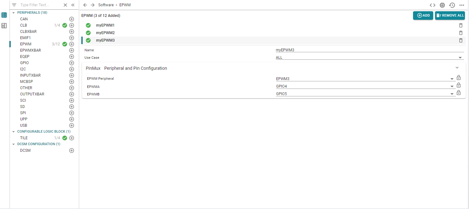
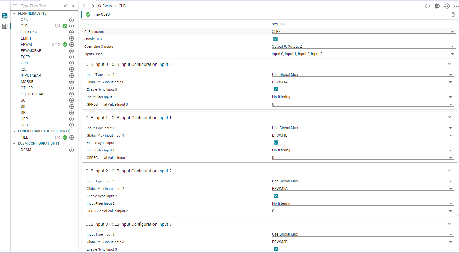
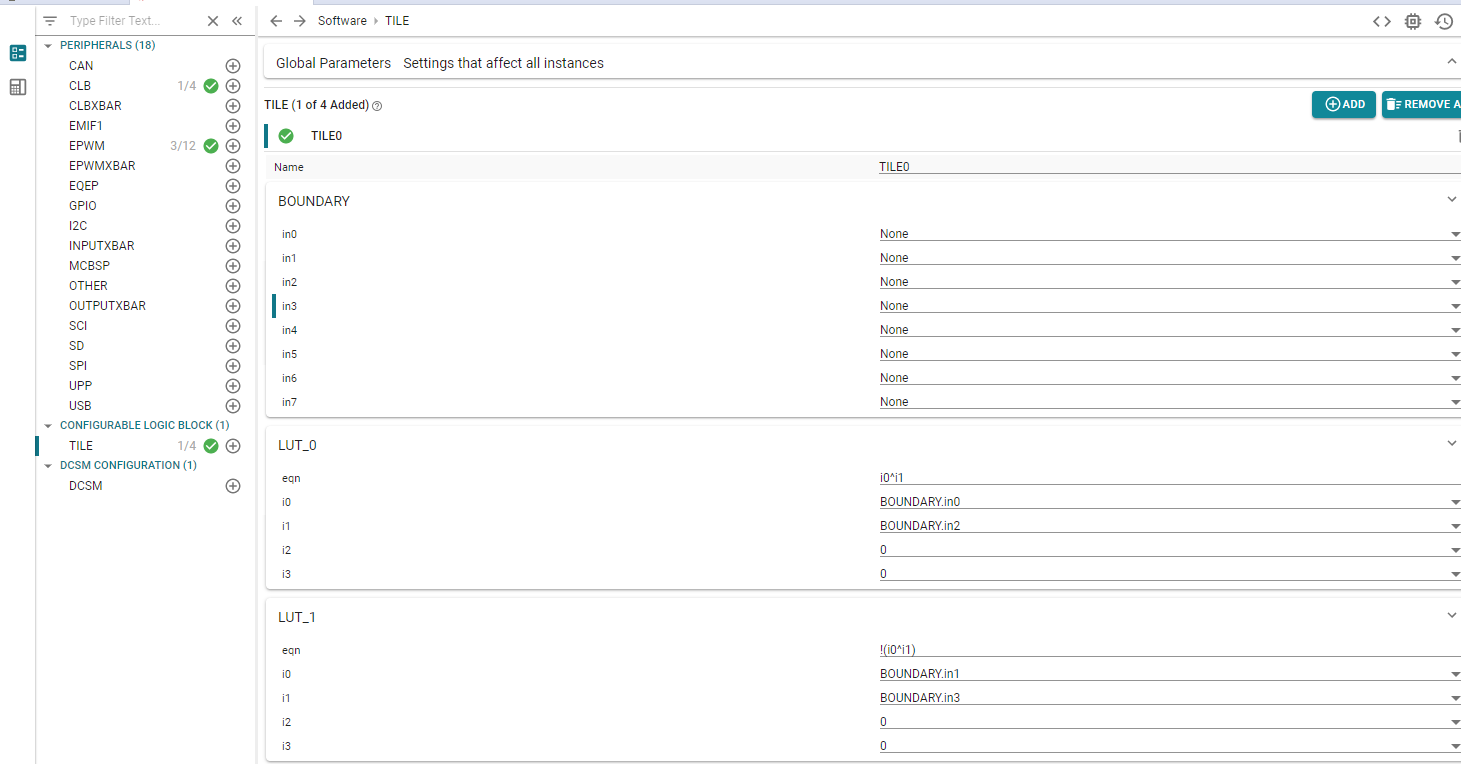
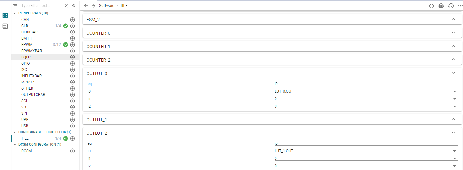
I want to use the CLB tool to generate a customised ePWM signal using ePWM internal peripherals of PWM1 and PWM2 and apply the following logic in a TIEL to produce PWM3A and PWM3B at pins GPIO4 and GPIO5 by using CLB overriding option.
(PWM3A= PWM1A XOR PWM2A ), and (PWM3B =PWM1B NXOR PWM2B )
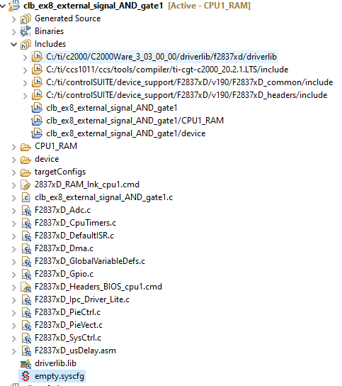
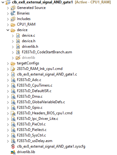
I modified the clb_ex8_external_signal_AND_gate CLB example and inserted a few additional codes to generate PWM1 and PWM2 signals as global signals.
However, I don't get the signals I am looking for. So please advice me?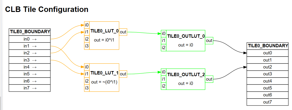


    #include "driverlib.h"
    #include "device.h"
    #include "clb_config.h"
    #include "clb.h"
    #include "board.h"
    #include "F28x_Project.h"


    void InitEPwm1(void);               // Init ePWM module 1
    void InitEPwm2(void);


    void main(void)
    {

        Device_init();
        Device_initGPIO();

        Interrupt_initModule();
        Interrupt_initVectorTable();


            InitEPwm1();    //
            InitEPwm2();    //


            SysCtl_enablePeripheral(SYSCTL_PERIPH_CLK_EPWM3);


        Board_init();

        initTILE1(myCLB0_BASE);
        CLB_enableCLB(myCLB0_BASE);


        while(1)
        {

            asm(" NOP");
        }
    }
    void InitEPwm1(void)
    {
        EPwm1Regs.TBPRD = 450; // Period = 900 TBCLK counts
        EPwm1Regs.TBPHS.bit.TBPHS = 0; // Set Phase register to zero
        EPwm1Regs.TBCTL.bit.CTRMODE = TB_COUNT_UPDOWN; // Symmetrical mode
        EPwm1Regs.TBCTL.bit.PHSEN = TB_DISABLE; // Master module
        EPwm1Regs.TBCTL.bit.PRDLD = TB_SHADOW;
        EPwm1Regs.TBCTL.bit.SYNCOSEL = TB_CTR_ZERO; // Sync down-stream module
        EPwm1Regs.CMPA.bit.CMPA= 285; // adjust duty for output EPWM1A
        EPwm1Regs.CMPCTL.bit.SHDWAMODE = CC_SHADOW;
        EPwm1Regs.CMPCTL.bit.SHDWBMODE = CC_SHADOW;
        EPwm1Regs.CMPCTL.bit.LOADAMODE = CC_CTR_ZERO; // load on CTR=Zero
        EPwm1Regs.CMPCTL.bit.LOADBMODE = CC_CTR_ZERO; // load on CTR=Zero
        EPwm1Regs.AQCTLA.bit.CAU = AQ_SET; // set actions for EPWM1A
        EPwm1Regs.AQCTLA.bit.CAD = AQ_CLEAR;
        EPwm1Regs.DBCTL.bit.OUT_MODE = DB_FULL_ENABLE; // enable Dead-band module
        EPwm1Regs.DBCTL.bit.POLSEL = DB_ACTV_HIC; // Active Hi complementary
        EPwm1Regs.DBRED.bit.DBRED = 20;    // Dead-Band Generator Rising Edge Delay Count Register
        EPwm1Regs.DBFED.bit.DBFED = 20;    // Dead-Band Generator Falling Edge Delay Count Register
    }

    //------------------------------------------------------------------------------------------
    void InitEPwm2(void)
    {
        EPwm2Regs.TBPRD = 450; // Period = 900 TBCLK counts
        EPwm2Regs.TBPHS.bit.TBPHS = 300; // Phase = 300/900 * 360 = 120 deg
        EPwm2Regs.TBCTL.bit.CTRMODE = TB_COUNT_UPDOWN; // Symmetrical mode
        EPwm2Regs.TBCTL.bit.PHSEN = TB_ENABLE; // Slave module
        EPwm2Regs.TBCTL.bit.PHSDIR = TB_DOWN; // Count DOWN on sync (=120 deg)
        EPwm2Regs.TBCTL.bit.PRDLD = TB_SHADOW;
        EPwm2Regs.TBCTL.bit.SYNCOSEL = TB_SYNC_IN; // sync flow-through
        EPwm2Regs.CMPA.bit.CMPA = 285; // adjust duty for output EPWM2A
        EPwm2Regs.CMPCTL.bit.SHDWAMODE = CC_SHADOW;
        EPwm2Regs.CMPCTL.bit.SHDWBMODE = CC_SHADOW;
        EPwm2Regs.CMPCTL.bit.LOADAMODE = CC_CTR_ZERO; // load on CTR=Zero
        EPwm2Regs.CMPCTL.bit.LOADBMODE = CC_CTR_ZERO; // load on CTR=Zero
        EPwm2Regs.AQCTLA.bit.CAU = AQ_SET; // set actions for EPWM2A
        EPwm2Regs.AQCTLA.bit.CAD = AQ_CLEAR;
        EPwm2Regs.DBCTL.bit.OUT_MODE = DB_FULL_ENABLE; // enable Dead-band module
        EPwm2Regs.DBCTL.bit.POLSEL = DB_ACTV_HIC; // Active Hi Complementary
        EPwm2Regs.DBRED.bit.DBRED = 20;    // Dead-Band Generator Rising Edge Delay Count Register
        EPwm2Regs.DBFED.bit.DBFED = 20;    // Dead-Band Generator Falling Edge Delay Count Register
    }