This thread has been locked.

If you have a related question, please click the "Ask a related question" button in the top right corner. The newly created question will be automatically linked to this question.

TMS320F28379D-Q1: error in programming Tms320f28379d controller custom board has been made utilizing schematics from f28379Launchpad..Blackhawk XDS560 system trace emulator

Part Number: TMS320F28379D-Q1
Other Parts Discussed in Thread: TMS320F28379D, LAUNCHXL-F28379D, C2000WARE

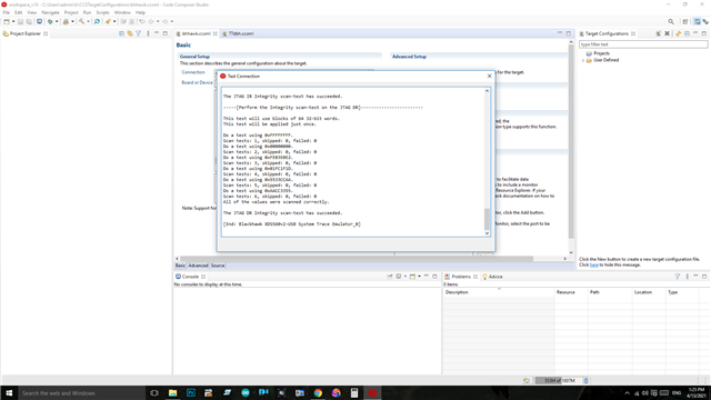
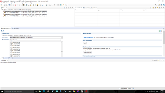
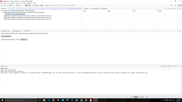
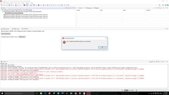
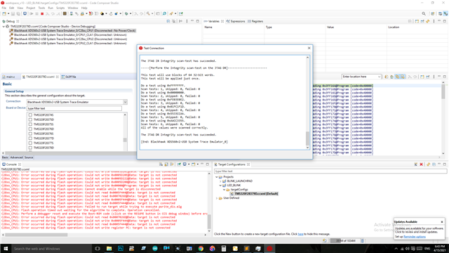
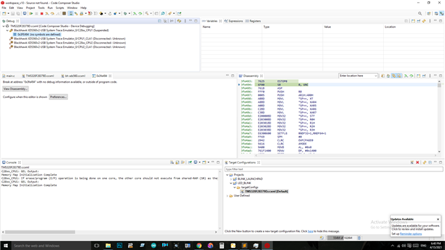
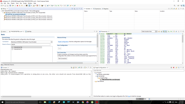
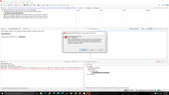
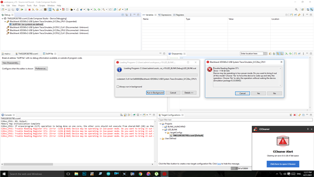
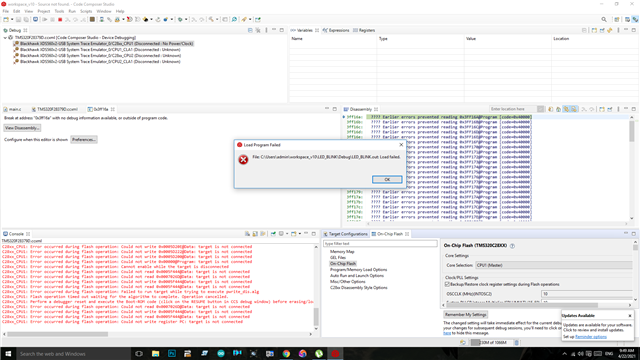
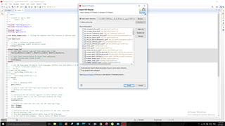
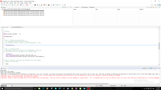
i am using Blackhawk XDS560 system trace emulator to program my custom board from ccs studio...Jtag tests are OK ..while programming it shows error. i also programmed my f28379 launchpad using BH xds560 by removing those isolators it programs well...my custom board throws following error.please help.

  • Hi,

    What is the boot-mode? Looks like it is booting from Flash? You may want to try wait-boot mode.

  • actually for boot modes i followed similar dip switches in launchpad..in ccs connecting to target itself throws error..only jtag test is passed...while trying to load .out file...itshows following error.it is in emu boot mode as in the launchpad.. it shows target connect after clicking "connect target" after launching debug mode

  • Hi,

    Error looks like, it is going to access flash. It will be good to put the board in wait boot mode and then try loading it.

  • i tried wait boot boode by changing the dip switches 010 as in the launchpad..this time Jtag test itself failed..can you tell me what else can do..i tried all the 8 combinations ..nothing working out...if trst is high then only jtag test is working fine or else jtag error..  how can i get local support  TI..

  • Looking at your first post/images, CCS is giving a warning that the detected device doesn't match the selected device.  From your 2nd image in the "basic" configuration; underneath the emulator selection of the XDS560 there is a space to select the device.  You'll need to pick the TMS320F28379D device from this list and save.

    The flash API does some cursory checks to make sure that the device ID matches what you have selected in CCS.  This is to make sure an use the correct timings and address ranges before using the flash.  Since there is not a device selected, I believe that CCS will prevent you from programming the device to avoid damage.

    Best,

    Matthew

  • i already configured .ccxml file same result, launching debug mode also produce same results i attach the result bellow. i again double checked hadware with 4 different boards in this minimum jtag configuration same results consuming 70-80 mA. what could we doing wrong??

  • with 4 different boards in this minimum jtag configuration same results consuming 70-80 mA

    Black Hawk or your custom PCB consume 70-80mA? Is MCU a Ball or TQFP foot print, have you try pin to pin ring test for shorts?

  • Another thing to look at is once you are connected to the device; open up the flash tools(Tools->On-Chip Flash tools).  Make sure that the clock settings are correct(these may be greyed out and using the internal oscillator which is OK).

    From there let's just "Erase" the flash and see if the same error pops up.

    If this is the case as GI said it would seem that we are current starving the device during flash program/erase operations.  You could check your VDD3VFL supply pin to make sure it is within the DS limits of 3.14V - 3.47V or drooping during flash operations.

    I'm assuming CCS is only throwing this error when we attempt flash program/erase, but please correct me if this is wrong.

    Best,

    Matthew

  • mcu custom board is consuming 70-80mA, i tested each pin to pin looking for shorts, no short found. pakage is tms320f28379ptps 176 pin pakage.

  • i connected my device as below screenshot it is ok..while erasing flash as you told me to do same error pops up...flash stting are default..i wonder why tms320c28xx on chip flash opens while i try to flash tms320f28379d...or vis it normal....3.3v on flash is solid...blanck check also produce same error..

    while try to load program error is produced..i can lauch debug configuration and connect to target thats all i can do..if i try to load .out or flash error is produced.

  • Perhaps MUC stuck in xRSN reset or MOSC/PLL is not running correct frequency? Matthew any advise about MCU high current demand?

  • GI,

    The flash tools should force use of the internal oscillator, although the PLL can be changed(should be at a 19); so I think we can rule that out at least for using the CCS tools.  

    Keerthi,

    You mentioned that your custom PCB was made using the LAUNCHXL-F28379D as a reference.  Is it correct to say that the LDOs and decaps on the power supplies are the same as the launchpad?  

    Would it be possible to share your schematic?  If you'd like to do so privately, you can "connect" to me and you can attach off forum via the private chat function.

    Also let's open a memory window to 0x78000(linkpointer) and make sure that is erased.  All devices should be erased from the factory, but I want to make sure of the state of everything.

    Best,
    Matthew

  • yes most of the comoponents are same and similar, but we have changed LDO for 3.3V and some minor modifiactions are done interms of parts..i "connect"ed you..i will share the schematics off the forum..

  • Keerthi,

    I just accepted the friend request.  Will look for the attachment in the private chat area.

    Best,

    Matthew

  • Sometimes solder paste produces tiny balls that get stuck between pins. The problem with most DMM <300Ω to ring and will not detect high impedance shorts but Ω scale will. Had that kind of short bite me in the past.

  • i had that issue in the past ..but i have cleared with high pressure pump and IPA, i have used RMA no clean paste but still i look again

  • I never used high pressure air but sounds like it could work too. Often use thinnest sewing needle drag lightly between pins, inspecting under 5x-10x magnification. Then again clean with flux off to remove any white/clear residue and to see better between pins. The opposite condition is poor pin wetting to pad contact can occur.

    Often use thin wedge tip iron with flux bath in pin area to get even re-flow, 290-300°C 1-2 seconds across several pins wait for flux smoke & hear sizzle popping both good indicators. Often find that melts tiny paste balls behind pins that remain out of sight between two or more pads, even via x10 magnification very difficult to see them. Please let forum know what your finding Wink  

  • Not high pressure air it is high pressure IPA.i will reflow once again with your suggestion and let you know the details

  • Never heard of HP-IPA but know when VDD/VDDA pins don't have good wetting to HASL pads some really strange things often occur with JTAG. Next boards I make will have gold contact TQFP layout after seeing how solder paste reacts to 0PB-HASL Nerd

  • i used high presure pump sparyer to clean PCB it works quite well i checked under 8X magnification.i am following this thread i cannot reset debugger after connecting to target(https://e2e.ti.com/support/microcontrollers/c2000/f/c2000-microcontrollers-forum/729543/faq-product-change-notice-pcn-20180523001-1-for-tms320f2837x-and-tms320f2807x-devices?tisearch=e2e-sitesearch&keymatch=faq%252525252525253Atrue) help me out

  • it works quite well

    99% DNA is not so cheep and some IPA may have ?% water, check label. Stick with flux off modified MEK made for PCB, IPA seemingly not.

    i cannot reset debugger after connecting to target

    I seriously doubt 80mA current draw is due to flash type. Unclear above comments do you use two wire 2WD or JTAG pins? Some of the XML debug emulations were configured for JTAG and 2WD will fail.

  • i use two type of 3.3Vs source in 2 different board, according to my final schematics i use lm63625. it draws 20mA current. another source is ams1117 it draws about 60-80mA current both are supplied via 12v bench supply.i meant iPA works well that no visual residue of flux or solder balls.i use only JTAG. in the above link they given certain procedure to flash f28379D $4 version thtas what i am using now..in that i couldnt follow the directions thats why i asked the question


  • Keerthi,

    Below is a screenshot(and here is the link to the DS) to the expected currents on each supply.  The last row is what will be needed by the device during flash programming.  Let's check the LDOs you have to make sure they can meet this demand.

    I'd like to try something a bit different, let's use some of the code examples in C2000Ware, but make sure the build configuration is set to RAM.  I would like to see if the device is stable running some of those examples w/o using the flash at all.  This will help us root cause where the error may be, either absolute current draw or just flash issues.

    GI,

    For continuity sake(from some off forum dialogue)  he's also used a XDS100v2 and gets the same results.  I think the JTAG is OK at this point.

    Best,

    Matthew

  • Several notes (7) and blank factory flash 53-65mA seems a bit obscure. Posted DS link is not working Wink. The RAM project load is excellent idea ClapClap    

    ams1117 it draws about 60-80mA current

    Have to imagine most any +3v3 LDO can source 300mA, AMS a switching buck regulator? If +3v3 buck regulator may require stacking ceramic caps on the output to arrest CBC current limit cycles? 

  • Link fixed, thanks for the heads up.

  • Keerthi,
    Wanted to check back in to see if you had any progress running the RAM only examples in C2000Ware?

    Best,

    Matthew

  • sure i ll do that and get back to u asap

  • i ran c2000 RAM blinky example..following is the result

  • its LDO cpable of 1A as per datasheet, we stack 10uf/1uf/100nf decoupling capacitors

  • Perhaps debug probe error has tried to 1st erase flash? Seemingly you can disable erase program (flash) for the Ram load test. This is why to disable erase flash on program load check box.

  • Keerthi,

    Sorry for the lack of reply from me here.  Its good that the RAM execution is working correctly; I think this points more toward some issue with the VDDIO/VDD3VFL supply at the device pins(not necessarily an issue with the LDO per se).

    I re-looked through the schematic you sent offline; and things look to be matching in terms of power decaps with the LAUNCHXL-F28379D, which is a good reference.  Would you be able to comment (or share off forum) the layout of your PCB, even a picture of the decaps so I can see the relative position to the C2000 device? 

    I would be looking for placement similar to the LAUNCHXL-F28379D, relatively close to the device.

    It may be a good idea to verify the cap values themselves to make sure that we are getting the right amount of capacitance that you intended in the schematic.  I've had issues in the lab where I've grabbed the next decade higher/lower of passives from stock and that can cause issues(I've also had issue with board manufactures loading the incorrect reel in the same way).

    Based on everything so far, esp with CCS killing the JTAG connection as soon as you attempt to do any operation with the flash, I still think this must be instantaneous current droop with demand on the IO rail(caused by the VDD3VFL pin/supply).

    Best,

    Matthew

  • The last screen captures unable to zoom but red text shows error unable to connect to target. Did the ram test truly succeed?