This thread has been locked.
If you have a related question, please click the "Ask a related question" button in the top right corner. The newly created question will be automatically linked to this question.
Dear Champs,
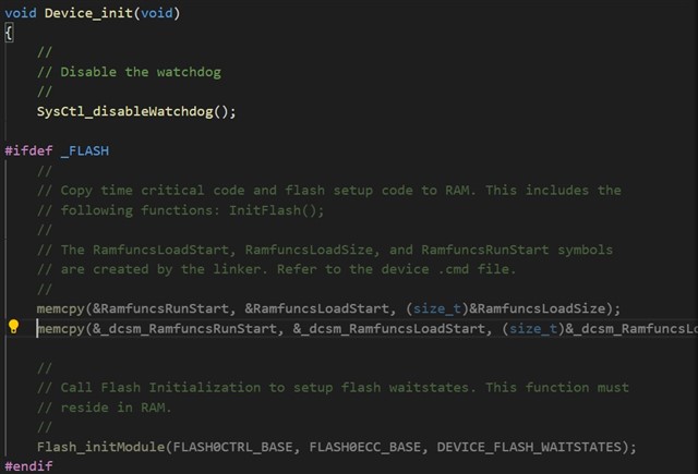
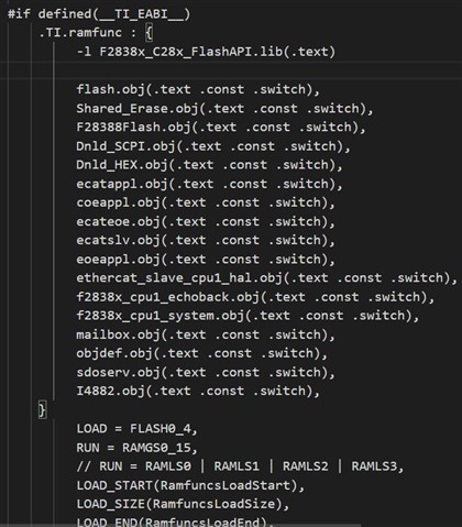
Customer tried to copy the code to run from secure zone in DCSM to normal Flash section but met crash result.
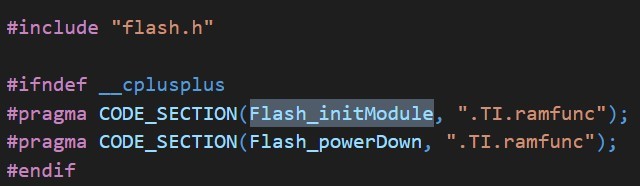
They configured "Device_init” in secure Flash by DCSM but met CPU crash when is running in Flash_initModule (in RAMGSx).
Does anyone have any suggestions for this issue? Because we can use this method in F2837x but always failed to crash in F2838x.
If you have any suggestions, please feel free to let me know.
Thanks a lot.
Best regards,
Janet
Hi Janet,
So in this case customer is copying some function (flash initialization) from secure flash to non-secure RAM. Correct ? If yes, can you confirm where the memcpy function is placed ? This should be in secure memory only to be able to copy data from secure flash. Please refer section "Usage of memcpy Function From the RTS Library" in this appnote for more detail on this.
Next thing to check is the security configuration of flash sector. There is a bit difference in configuration value if using both the zone. If using only one zone then this should not matter as long as other zone is unsecure (done by BOOTROM code for default passwords).
Regards,
Vivek Singh
Hi Janet.
Let me know if you have any further queries on this topic.
Regards,
Vivek Singh
Dear Vivek,
Thanks for your following up.
Our customer will explain their detail concerns later.
Thanks a lot.
Best regards,
Janet
Dear Vivek,
Yes, we had check memcpy(rts2800_fpu64_eabi.lib) in flash2( address 0x0008285D), even, we try to use a for loop copy code to global ram, it still crash at jump to Flash_initModule function.
We had try a sample as follow. In this case, We try to make all the code in secure Flash by DCSM. After DCSM, this code will not work, continuous trigger reset(XRS) and reboot. Hope this code is helpful to this topic.
#include "device.h" #include "driverlib.h" #define ON 1 #define OFF 0 #define GPIO_PIN_LED_RED 34 void Init_GPIO(void) { // // Enable a GPIO output on GPIO6, set it high // GPIO_setPadConfig(GPIO_PIN_LED_RED, GPIO_PIN_TYPE_PULLUP); // Enable pullup on GPIO6 GPIO_writePin(GPIO_PIN_LED_RED, ON); // Load output latch GPIO_setPinConfig(GPIO_34_GPIO34); // GPIO6 = GPIO6 GPIO_setDirectionMode(GPIO_PIN_LED_RED, GPIO_DIR_MODE_OUT); // GPIO6 = output } void delayMS(uint32_t t) { int i; for(i=0;i<t;++i) { DEVICE_DELAY_US(1000); } } int main(void) { // // Initialize device clock and peripherals // Device_init(); // // Disable pin locks and enable internal pull-ups. // Device_initGPIO(); // // Initialize PIE and clear PIE registers. Disables CPU interrupts. // Interrupt_initModule(); // // Initialize the PIE vector table with pointers to the shell Interrupt // Service Routines (ISR). // Interrupt_initVectorTable(); // // Initialize other function // Init_GPIO(); while(1) { GPIO_writePin(GPIO_PIN_LED_RED, ON); delayMS(500); GPIO_writePin(GPIO_PIN_LED_RED, OFF); delayMS(500); } return 0; }
MEMORY { /* BEGIN is used for the "boot to Flash" bootloader mode */ BEGIN : origin = 0x080000, length = 0x000004 BOOT_RSVD : origin = 0x000002, length = 0x0001AE /* Part of M0, BOOT rom will use this for stack */ RAMM0 : origin = 0x0001B0, length = 0x000250 RAMM1 : origin = 0x000400, length = 0x000400 /* on-chip RAM block M1 */ RAMD0_1 : origin = 0x00C000, length = 0x001000 RAMLS0_1 : origin = 0x008000, length = 0x001000 RAMLS2_7 : origin = 0x009000, length = 0x003000 RAMGS0_15 : origin = 0x00D000, length = 0x010000 /* Flash sectors */ FLASH0_4 : origin = 0x080004, length = 0x00FFFC /* on-chip Flash */ FLASH5_8 : origin = 0x090004, length = 0x01FFFC /* on-chip Flash */ FLASH9_12 : origin = 0x0B0000, length = 0x00E000 /* on-chip Flash */ FLASH13 : origin = 0x0BE000, length = 0x002000 /* on-chip Flash */ CPU1TOCPU2RAM : origin = 0x03A000, length = 0x000800 CPU2TOCPU1RAM : origin = 0x03B000, length = 0x000800 CPUTOCMRAM : origin = 0x039000, length = 0x000800 CMTOCPURAM : origin = 0x038000, length = 0x000800 CANA_MSG_RAM : origin = 0x049000, length = 0x000800 CANB_MSG_RAM : origin = 0x04B000, length = 0x000800 RESET : origin = 0x3FFFC0, length = 0x000002 } SECTIONS { codestart : > BEGIN ,PAGE = 0, ALIGN(4) .text : >> FLASH0_4,PAGE = 0, ALIGN(4) .cinit : > FLASH0_4,PAGE = 0, ALIGN(4) .switch : > FLASH0_4, PAGE = 0,ALIGN(4) .reset : > RESET, TYPE = DSECT /* not used, */ .stack : > RAMD0_1 dcsm_data_section : > RAMLS2_7 PAGE = 0 #if defined(__TI_EABI__) .init_array : > FLASH0_4, ALIGN(4) .bss : > RAMGS0_15 .bss:output : > RAMGS0_15 .bss:cio : > RAMGS0_15 .data : > RAMGS0_15 .sysmem : > RAMGS0_15 /* Initalized sections go in Flash */ .const : > FLASH0_4, ALIGN(4) #else .pinit : > FLASH1, ALIGN(4) .ebss : > RAMLS5 .esysmem : > RAMLS5 .cio : > RAMLS5 /* Initalized sections go in Flash */ .econst : >> FLASH4 | FLASH5, ALIGN(4) #endif MSGRAM_CPU1_TO_CPU2 : > CPU1TOCPU2RAM, type=NOINIT MSGRAM_CPU2_TO_CPU1 : > CPU2TOCPU1RAM, type=NOINIT MSGRAM_CPU_TO_CM : > CPUTOCMRAM, type=NOINIT MSGRAM_CM_TO_CPU : > CMTOCPURAM, type=NOINIT #if defined(__TI_EABI__) .TI.ramfunc : {} LOAD = FLASH0_4, RUN = RAMGS0 | RAMGS1 | RAMGS2 |RAMGS3, LOAD_START(RamfuncsLoadStart), LOAD_SIZE(RamfuncsLoadSize), LOAD_END(RamfuncsLoadEnd), RUN_START(RamfuncsRunStart), RUN_SIZE(RamfuncsRunSize), RUN_END(RamfuncsRunEnd), ALIGN(4) #else .TI.ramfunc : {} LOAD = FLASH3, RUN = RAMLS0 | RAMLS1 | RAMLS2 |RAMLS3, LOAD_START(_RamfuncsLoadStart), LOAD_SIZE(_RamfuncsLoadSize), LOAD_END(_RamfuncsLoadEnd), RUN_START(_RamfuncsRunStart), RUN_SIZE(_RamfuncsRunSize), RUN_END(_RamfuncsRunEnd), ALIGN(4) #endif }
.sect "dcsm_z1otp_link_pointer" .retain .long 0x00003FFF ;Z1OTP_LINKPOINTER1 .long 0x00003FFF ;Z1OTP_LINKPOINTER2 .long 0x00003FFF ;Z1OTP_LINKPOINTER3 .sect "dcsm_z1otp_jlm_enable" .retain .long 0xFFFF000F ;Z1OTP_JLM_ENABLE .sect "dcsm_z1otp_gpreg" .retain .long 0xFFFFFFFF ;Z1OTP_GPREG1 .long 0xFFFFFFFF ;Z1OTP_GPREG2 .long 0xFFFFFFFF ;Z1OTP_GPREG3 .long 0xFFFFFFFF ;Z1OTP_GPREG4 .sect "dcsm_z1otp_pswd_lock" .retain .long 0x007FFFFF ;Z1OTP_PSWDLOCK .sect "dcsm_z1otp_crc_lock" .retain .long 0x7FFFFFFF ;Z1OTP_CRCLOCK .sect "dcsm_z1otp_jtag_pswdh" .retain .long 0x4bFFFFFF ;Z1OTP_JTAGPSWDH0 .long 0x3FFFFFFF ;Z1OTP_JTAGPSWDH1 .sect "dcsm_z1otp_cmac_key" .retain .long 0xFFFFFFFF ;Z1OTP_CMACKEY0 .long 0xFFFFFFFF ;Z1OTP_CMACKEY1 .long 0xFFFFFFFF ;Z1OTP_CMACKEY2 .long 0xFFFFFFFF ;Z1OTP_CMACKEY3 .sect "dcsm_zsel_z1" .retain .long 0x87654321 ;Z1OTP_CSMPSWD0 (LSW of 128-bit password) .long 0x4D770000 ;Z1OTP_CSMPSWD1 .long 0x12345678 ;Z1OTP_CSMPSWD2 .long 0x19916140 ;Z1OTP_CSMPSWD3 (MSW of 128-bit password) .long 0x05555555 ;Z1OTP_GRABSECT1 CPU1 flash : ALL .long 0x0FFFFFFF ;Z1OTP_GRABSECT2 CM core .long 0x0FFFFFFF ;Z1OTP_GRABSECT3 CPU2 flash .long 0x00055555 ;Z1OTP_GRABRAM1 .long 0xFFFFFF0F ;Z1OTP_GRABRAM2 .long 0x000FFFFF ;Z1OTP_GRABRAM3 ;; .long 0x3FFF3FFF ;Z1OTP_EXEONLYSECT1 ;; .long 0x00003FFF ;Z1OTP_EXEONLYSECT2 ;; .long 0xFFC303FF ;Z1OTP_EXEONLYRAM1 ;; .long 0xFFFFFFFF ;Reserved ;; .long 0xFFFFFFFF ;Z1OTP_JTAGPSWDL0 ;; .long 0x27FFFFFF ;Z1OTP_JTAGPSWDL1
Regards,
Kenny Jhan
Did you check if the code is getting copied correctly ? You can do that by halting CPU at Flash_initModule function and then unlocking the zone and check the value.
Regards,
Vivek Singh
Dear Vivek,
If I connected XDS200 (unlock DCSM), it copied correctly. If not, it will crash and reboot. When lanch and load symbols RAMGS0(0xD000) hacen't any data, and code stay in function _Fapi_setupFlashStateMachine (F2838x_C28x_FlashAPI.lib).
When lanch and load symbols RAMGS0(0xD000) hacen't any data, and code stay in function _Fapi_setupFlashStateMachine (F2838x_C28x_FlashAPI.lib).
This is strange because if code is not getting copied then CPU should on stay in flash setup function. In this case an ITRAP will happen and CPU will jump to ITRAP handler in BOOTROM.
Can you follow below steps -
After CPU halts at breakpoint, open the GSRAM location in memory watch window and see if any data is copied.
Regards,
Vivek Singh
Dear Vivek,
I think there have something wrong. It stay in RAMGS0 when I unlock DCSM. My detailed steps are as follows:
1. Download code and re-power on development board
2. (Now, XRS continuous trigger,) pull low GPIO72 to stay in wait boot mode
3. Open CCS and lanch chip
4. Connect C28xx_CPU1 and load symbol
5. Push Icon "CPU Reset" (Break at address "0x3fd2ae" with no debug information available, or outside of program code)
6. Open "Memory Browser", switch address to 0xD00 and write 0B5A
7. Open "Memory Map"->"On-Chop Flash"
8. Type CSMPSWD and unlock (Break at address "0xd058" with no debug information available, or outside of program code.)
9. Set the hardware breakpoint at function Flash_initModule
10. Push Icon "Resume" (Break at address "0x3fe96f" with no debug information available, or outside of program code.) --> ESTOP0
11. Open the RAMGS0 location (0xD000) in "memory Browser", the data is all 0x0000
Regards,
Kenny Jhan
Hi,
8. Type CSMPSWD and unlock (Break at address "0xd058" with no debug information available, or outside of program code.)
You should use CCS register view to enter the password and not via CCS On-Chip flash plug-in GUI because that one is used before loading the program.
Also if you look the steps I mentioned, I requested you to only enter KEY0 and KEY1 (64bit value) to unlock ECSL and not full security. Please try this the correct steps and let me know the result.
Regards,
Vivek Singh
Dear Vivek,
I correction step 8. Use register view to write Z1_CSMKET0 and Z1_CSMKEY1. After I set hardware breakpoint , I push Icon "Resume". XRS(Reset) pin trigger and reset power. Even I set hardware breakpoint on fist line (Device_init) after it jumps to main, I get same result...
Regards,
Kenny Jhan
Hi,
That means issue is happening even before memcpy ? Earlier you mentioned that code get stuck in flash function. Let me request Janet to setup a webex session to look into this.
Regards,
Vivek Singh
Dear Vivek,
Maybe yes in this result...But if I change .TI.ramfunc run in RAMLS0_1(now work in RAMGS0_15) , it will work well, cmd file as follow(Output format is eabi). And I try to remove the function in .TI.ramfunc section. it also work.
MEMORY { /* BEGIN is used for the "boot to Flash" bootloader mode */ BEGIN : origin = 0x080000, length = 0x000004 BOOT_RSVD : origin = 0x000002, length = 0x0001AE /* Part of M0, BOOT rom will use this for stack */ RAMM0 : origin = 0x0001B0, length = 0x000250 RAMM1 : origin = 0x000400, length = 0x000400 /* on-chip RAM block M1 */ RAMD0_1 : origin = 0x00C000, length = 0x001000 RAMLS0_1 : origin = 0x008000, length = 0x001000 RAMLS2_7 : origin = 0x009000, length = 0x003000 RAMGS0_15 : origin = 0x00D000, length = 0x010000 /* Flash sectors */ FLASH0_4 : origin = 0x080004, length = 0x00FFFC /* on-chip Flash */ FLASH5_8 : origin = 0x090004, length = 0x01FFFC /* on-chip Flash */ FLASH9_12 : origin = 0x0B0000, length = 0x00E000 /* on-chip Flash */ FLASH13 : origin = 0x0BE000, length = 0x002000 /* on-chip Flash */ CPU1TOCPU2RAM : origin = 0x03A000, length = 0x000800 CPU2TOCPU1RAM : origin = 0x03B000, length = 0x000800 CPUTOCMRAM : origin = 0x039000, length = 0x000800 CMTOCPURAM : origin = 0x038000, length = 0x000800 CANA_MSG_RAM : origin = 0x049000, length = 0x000800 CANB_MSG_RAM : origin = 0x04B000, length = 0x000800 RESET : origin = 0x3FFFC0, length = 0x000002 } SECTIONS { codestart : > BEGIN ,PAGE = 0, ALIGN(4) .text : >> FLASH0_4,PAGE = 0, ALIGN(4) .cinit : > FLASH0_4,PAGE = 0, ALIGN(4) .switch : > FLASH0_4, PAGE = 0,ALIGN(4) .reset : > RESET, TYPE = DSECT /* not used, */ .stack : > RAMD0_1 dcsm_data_section : > RAMLS2_7 PAGE = 0 #if defined(__TI_EABI__) .init_array : > FLASH0_4, ALIGN(4) .bss : > RAMGS0_15 .bss:output : > RAMGS0_15 .bss:cio : > RAMGS0_15 .data : > RAMGS0_15 .sysmem : > RAMGS0_15 /* Initalized sections go in Flash */ .const : > FLASH0_4, ALIGN(4) #else .pinit : > FLASH1, ALIGN(4) .ebss : > RAMLS5 .esysmem : > RAMLS5 .cio : > RAMLS5 /* Initalized sections go in Flash */ .econst : >> FLASH4 | FLASH5, ALIGN(4) #endif MSGRAM_CPU1_TO_CPU2 : > CPU1TOCPU2RAM, type=NOINIT MSGRAM_CPU2_TO_CPU1 : > CPU2TOCPU1RAM, type=NOINIT MSGRAM_CPU_TO_CM : > CPUTOCMRAM, type=NOINIT MSGRAM_CM_TO_CPU : > CMTOCPURAM, type=NOINIT #if defined(__TI_EABI__) .TI.ramfunc : {} LOAD = FLASH0_4, RUN = RAMGS0_15, LOAD_START(RamfuncsLoadStart), LOAD_SIZE(RamfuncsLoadSize), LOAD_END(RamfuncsLoadEnd), RUN_START(RamfuncsRunStart), RUN_SIZE(RamfuncsRunSize), RUN_END(RamfuncsRunEnd), ALIGN(4) #else .TI.ramfunc : {} LOAD = FLASH3, RUN = RAMLS0 | RAMLS1 | RAMLS2 |RAMLS3, LOAD_START(_RamfuncsLoadStart), LOAD_SIZE(_RamfuncsLoadSize), LOAD_END(_RamfuncsLoadEnd), RUN_START(_RamfuncsRunStart), RUN_SIZE(_RamfuncsRunSize), RUN_END(_RamfuncsRunEnd), ALIGN(4) #endif } /* //=========================================================================== // End of file. //=========================================================================== */
Regards,
Kenny Jhan
Stack was placed in secure RAM hence it was not working. Once stack was moved into non-secure RAM, it worked fine.
Dear Vivek,
Thanks for your help.
I found this reminder in compiler user guide that said "The .stack section has to be linked into the low 64K of data memory in M0/M0 rather than other RAM section" and problem was solved.
Many thanks.
Best regards,
Janet