This thread has been locked.

If you have a related question, please click the "Ask a related question" button in the top right corner. The newly created question will be automatically linked to this question.

C28 Core not running in standalone.

Other Parts Discussed in Thread: CONTROLSUITE

Hello,

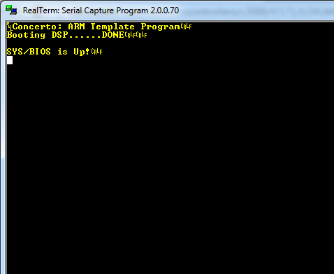
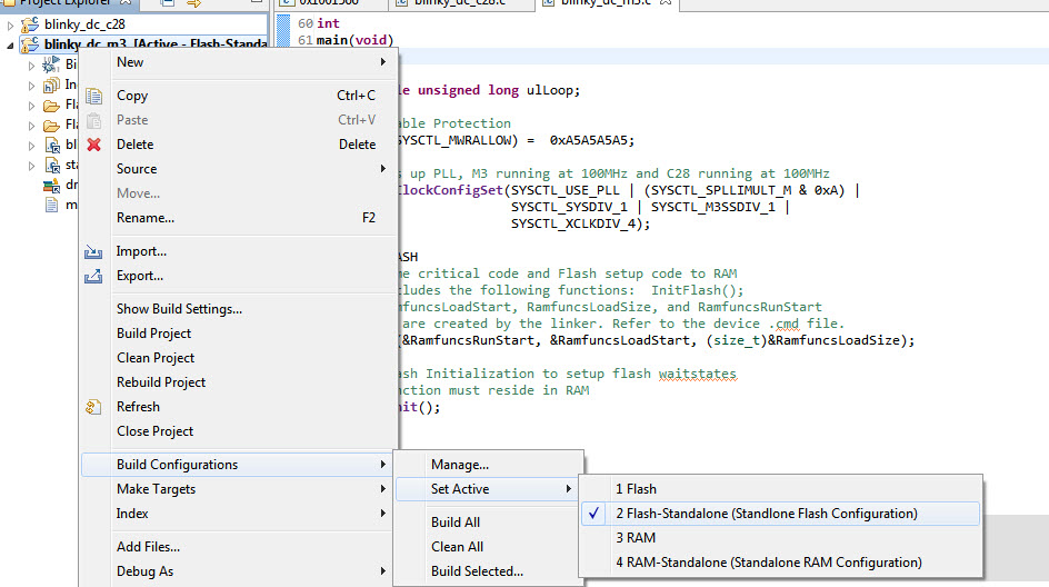
I have loaded the dual core blinky example and upon reset the device only blinks the LED for the m3. This is the same behavior that is demonstrated when using my code. The C28 core does not execute the program when booted by the master system after reset.

For both projects the code works properly when the debugger is attached. I can verify that the IPC command to boot the dsp is completing without error when using my code.

Code Composer Studio

Version: 5.3.0.00090

IPC 1.25.01.09

xdctools 3.24.05.48

bios 6.34.04.22

  • Why does TI not respond to posts???

    When you call tech support they point you toward the forum. They then ignore the post.

    I guess I'm small fries, less than a dozen units sold. Why would they care to help me?

    Meanwhile, I still have the problem and there is no help from TI


    // boot the DSP
    DebugOut("Booting DSP...");
    if (IPCMtoCBootControlSystem(CBROM_MTOC_BOOTMODE_BOOT_FROM_FLASH))
    {
    DebugOut("Boot Failed!\tTry from RAM...");
    // Send boot command to allow the C28 application to begin execution
    if (IPCMtoCBootControlSystem(CBROM_MTOC_BOOTMODE_BOOT_FROM_RAM)) DebugOut("Failed!\r\n");
    else DebugOut("Boot OK!\r\n");
    }
    else DebugOut("...DONE\r\n\r\n");


  • Nick,

    TI does in fact respond to posts.  We are all very passionate about helping all of our customers, big or small. I apologize if your first post slipped through the cracks.  The same people that answer forum posts also have many other duties (such as designing chips and writing software for them).  It's delicate balance between supporting our customers and getting our work done developing new devices.

    Given what you've shown above it does in fact sound like your program is working correctly on the M3 and that you are successfully booting up the C28.  Is you C28 code setup to have the correct entry point for a flash boot?  The IPC call to boot the C28 will not return unless it is successful.

    Trey

  • Post #1 (no response by TI)

    http://e2e.ti.com/support/microcontrollers/c2000/f/171/p/236312/828650.aspx#828650

    Post #2 (no response)

    http://e2e.ti.com/support/microcontrollers/c2000/f/171/p/237797/833662.aspx#833662

    Post #3 (unresolved)

    http://e2e.ti.com/support/development_tools/code_composer_studio/f/81/p/238785/840481.aspx#840481


    This is the 4th post on the subject! Not to mention the 3 tech. support calls made by my wife to get someone to look at my posts.

    I am still unable to program the DSP on two boards. I still can't get DSP code to run in standalone on any board. I know the DSP code is sound because it runs under the debugger without error. One interesting thing to me is that the code will only run with the following process:

    with debugger connected: [reset -> restart -> run]

    If I do: [reset -> run] the program does not run correctly.

    Thanks for the response, finally.

    Update: from project.map

    .ti_catalog_c2800_concertoInit_begin 
    * 0 0013fff0 00000002 
    0013fff0 00000002 Boot.a28FP : Boot_asm.o28FP (.ti_catalog_c2800_concertoInit_begin)

    I believe this points the boot rom at main???

  • Nick Neander said:

    with debugger connected: [reset -> restart -> run]

    If I do: [reset -> run] the program does not run correctly.

    Nick - the difference between the two is in the case of a restart CCS will force the PC to what it thinks the entry point of the code is - this entry point will be in the application and therefore you bypass the boot ROM completely.   Performing a reset->run is more like a stand alone application where the reset of the device determines the start PC location which is indeed in the ROM.

    • Please check that the boot mode pins are correct for a boot to Flash.   If they are set to another mode it is possible the boot ROM is waiting for a SCI packet or something else.
    • If you set a breakpoint at the entry point to flash, then perform a reset -> run do you ever make it to the breakpoint?   This will help us understand if you are never even making it to flash or if the processor resets so you endup back in the ROM.

    Thank you

    Lori

  • Nick,

    Are you able to execute a non-bios project from flash?

    I am wondering if you are encountering the issue at the end of this thread with the BIOS boot:

    http://e2e.ti.com/support/microcontrollers/c2000/f/171/t/244588.aspx

    Regards

    Lori

  • No, non-bios does not run in stand alone. One of the previous posts stated that I tried the blinky dual core example and found the same results.

    I can tell you that main() is never reached when in stand alone or reset by debugger. I have the led turn on as the first instruction.

  • Nick Neander said:

    No, non-bios does not run in stand alone. One of the previous posts stated that I tried the blinky dual core example and found the same results.

    I can tell you that main() is never reached when in stand alone or reset by debugger. I have the led turn on as the first instruction.

    Nick,

    Thank you for the confirmation.  If I understand this is on the 28x side (the M3 is booting - is that correct?).  Is this an M36x or a M35x?   And is it our controlCard or a custom board? 

    I will try to reproduce the issue here.

    Regards

    Lori

  • F28m35, control card, and the m3 is running fine (sometimes the clock appears to be slow)

    If you look at the earlier post you will see an excerpt of the m3 code and the fact that c28 rom is sending the ipc signal that boot was successful.

    In regards to the other forum, I am using ipc message rams when bios starts butnthe c28 is never getting there... 

  • Nick,

    For the M3 project, please check that you have selected the Flash-Standalone build configuration.  To check this, right click on the project in project explorer -> build configurations, set active -> flash-standalone.

    For the 28x project it is just the "Flash" configuration.

    The controlCARD I have here is blinking both LEDs from a power-on reset (no debugger).  I am using v160 of the dual core blinky example.

    Regards,

    Lori

  • Nick,

    Another note - there is an errata for "boot to Flash" when the debugger is connected.  It is described in www.ti.com/lit/SPRZ357

  • Thanks, I knew about the errata. It gave me a headache early on. I designed a work around so the m3 would skip the boot command if the gel file loaded a value ia a specific mem location.

    I will give the build config a try tonight. Have a nice weekend and thanks for the help.

  • There is no option to set the flash mode in the project.

    I did get the blinky example to run on both cores. My question is why did it work? One thing I noticed is the example had code_start defined and my program doesn't. linker.cmd places .ti_catalog_c2800_concertoInit_begin at the flash address 0x13fff0. I put a break point at that address in the disassembly and the PC never gets there.

    from the disassembly:

    3ff6b3: 767FF6B7 LCR 0x3ff6b7
    3ff6b5: FE82 SUBB SP, #2
    3ff6b6: 0006 LRETR
    3ff6b7: 7621 IDLE   <= the PC never leaves this instruction

  • More notes:

    I used my m3 code and the example blinky dsp code and both cores are running good standalone.

    I created a new RTOS project with the wizard and programmed it on the target. I made no changes to the project and it does not run with a reset -> run! Maybe you could try to recreate this behavior. I used the c28 specific Task project.

    I stepped through the rom and the PC never gets sent to the boot address (0x0013FFF0). I have a breakpoint set for the rom address (0x003FF6B3). This instruction calls a  routine that goes nowhere simply and IDLE instruction.

  • Nick Neander said:
    There is no option to set the flash mode in the project.

    Hi Nick,

    Due to the resolution of the screenshot I'm not able to see which project that is.   Is it the M3 blinky from controlSUITE?  If yes - then it seems you have imported an old version of the example.  The latest version 1.60 has 4 build configurations - RAM, RAM-standalone, FLASH and FLASH-Stanalone. 

    I want to make sure we have a good boot without BIOS before we go down the BIOS path.

    Thank you

    Lori

    edit: there are 4 build configurations not 3

  • Nick Neander said:

    I created a new RTOS project with the wizard and programmed it on the target. I made no changes to the project and it does not run with a reset -> run! Maybe you could try to recreate this behavior. I used the c28 specific Task project.

    I stepped through the rom and the PC never gets sent to the boot address (0x0013FFF0). I have a breakpoint set for the rom address (0x003FF6B3). This instruction calls a  routine that goes nowhere simply and IDLE instruction.

    Nick,

    I'll loop in a BIOS expert and see if they have any input.

    Regards

    Lori

  • I think you saw the part where I said both cores are working when the C28 code in nonRTOS.

    Have you verified the RTOS behavior on your end?

    My m3 project is the one that doesn't have the build options...

  • Nick Neander said:
    I think you saw the part where I said both cores are working when the C28 code in nonRTOS.

    Nick,

    Yes - but I am always a bit uneasy when things just start working :)  especially with old versions - will they suddenly stop working?

    Nick Neander said:
    Have you verified the RTOS behavior on your end?

    I have a query into the BIOS team at the moment. 

    -Lori

  • I think the reason the blinky example didn't work before is the build config. The m3 code wasn't booting the c28. It seems like the flash-standalone config was made as a workaround to rom errata..

    Now that I'm using my m3 code that always tries to boot the c28, I'm seeing the example c28 code run properly. Is there an example that uses the RTOS?

  • Hi Nick,

    I believe you can find a SYS/BIOS project using the TI Resource Explorer. (See SYS/BIOS -> ARM -> 28M35x Concerto -> F28M35H52C1->Typical)

    I can't recall why, but for some reason on Concerto devices the default behavior for SYS/BIOS on the M3 is not to boot the C28 core.

    In a SYS/BIOS CCS project, you should able to find a .cfg file. By adding this into your .cfg file (for the M3 core) it should do the trick:

    var Boot = xdc.useModule('ti.catalog.arm.cortexm3.concertoInit.Boot');

    Boot.bootC28 = true;

    I don't think that the C28 core needs to be running SYS/BIOS for it to boot up.

  • As I stated, the m3 code is working fine and when the c28 is running non RTOS code (the blinky example) both cores run fin standalone.

    The current issue is that an RTOS C28 project won't run standalone.

  • Nick Neander said:

    As I stated, the m3 code is working fine and when the c28 is running non RTOS code (the blinky example) both cores run fin standalone.

    The current issue is that an RTOS C28 project won't run standalone.

    Nick,

    Yes, I understand, the 28x is not booting stand-alone to flash properly.    If this is the case, we suspect that the M3 is not telling the 28x it to do so.

    The M3 will only tell the 28x to boot if the following is in the .cfg file for the M3 project -

    var Boot = xdc.useModule('ti.catalog.arm.cortexm3.concertoInit.Boot');

    Boot.bootC28 = true;

    Thank you

    Lori


  • I added the lines to the .cfg file for the m3. Now neither core is running stand alone.

    The m3 is now hung when running the debugger. After a restart the PC is not at main, see below:

  • Nick,

    I'm also having trouble in getting the dual core controlSUITE (nonBIOS) blinky examples to run from a power-cycle (the c28 isn't blinking).

    I was however able to get a SYS/BIOS applications to boot from flash from both C28 and M3. For SYS/BIOS projects, I took a closer look at the boot modules. To allow the M3 to boot the C28, the C28 should also have the C28 boot module enabled (using SYS/BIOS). The C28 boot module has a "boot from Flash" option, which causes the C28 to branch to the application entry point (with SYS/BIOS its _c_int00).

    C28 .cfg:

    var Boot = xdc.useModule('ti.catalog.c2800.concertoInit.Boot');

    M3 .cfg:

    var Boot = xdc.useModule('ti.catalog.arm.cortexm3.concertoInit.Boot');

    Boot.bootC28 = true;

    I've attached a set of .out files that worked for me to get both cores up and running with SYS/BIOS. Can you test your board with these files?

    8836.sysbios_blinky_set.zip

  • Nick,

    I stand corrected, the dual core controlSUITE examples also worked for me when I used the M3's "Flash-Standalone" build configuration.

  • Does the bootC28 = true line replace the call from m3 code to boot the control system?

  • Nick Neander said:

    Does the bootC28 = true line replace the call from m3 code to boot the control system?

    Correct. If you are using SYS/BIOS on the C28 and M3, then you can (but it is not required) let the boot module handle this and you wouldn't need controlSUITE's IPCMtoCBootControlSystem() call on the M3.

    If either C28 or M3 is not using SYS/BIOS, then you probably will want to use controlSUITE's API's on both cores.

  • SUCCESS!!!

    I have the ability to debug both cores and they both run stand alone.

    NOTE: The use of the controllSUITE api and the bios boot functionality are exclusive. You cannot use the api if your letting the bios boot the control system.

    Thanks to Tom, Lori, and Trey for all the help. I really appreciate you all sticking with me.

    God Bless

    Nick

  • Nick Neander said:

    SUCCESS!!!

    I have the ability to debug both cores and they both run stand alone.

    Nick - Great!!!  

    This needs to be clear in our collateral.  I need to put some thought into how to make it so.  

    Nick Neander said:

    I really appreciate you all sticking with me.

    I appreciate you sticking with us while we dug into this! 

    Happy coding

    Lori