This thread has been locked.
If you have a related question, please click the "Ask a related question" button in the top right corner. The newly created question will be automatically linked to this question.
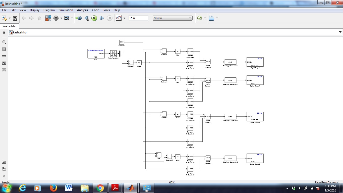
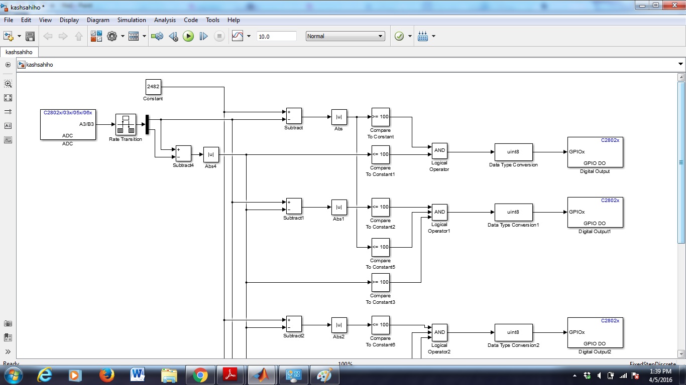
I;m working on f28027 micro-controller and trying to code it using simulink.........First I tried to configure an ADC in Simulink and build it, the code runs fine on c2000 but the changes are not made in the real time in the ADC output, only after stopping the changes are made in the memory blks......aslo I want to compare 2 ADC signals, for that which simulink blk should I use?????.........I want to multiply 2 ADC signals too....I want to multiply ADC with a constant blk to read the measured values, so how I have to configure the constant block to match the data types and multiply........Please help me out in this, Its urgent......Is there anyone I can contact and can help me out in this?
the changes are not made in the real time in the ADC output, only after stopping the changes are made in the memory blks:
try graph functionality of CCS to visualize real-time changes.
I want to compare 2 ADC signals, for that which simulink blk should I use?????:
compare block of simulink library. give output of channels to its' input port.
I want to multiply 2 ADC signals too:
use product block or dedicated TI block for multiplication.
how I have to configure the constant block to match the data types and multiply:
there is functionality to set data type of output in ADC block. match it with data type of constant block.
Thank u sir fro ur reply....Why the changes are not made in the real time in ADC output, as I want continuous changes as I m calculating Power.....In one of the tutorial which done using coding, their changes are made in the real time in the ADC output....where is graph functionality available??....
Whats the use of continuous refresh?
you try that. you will come to know. it is very helpful for what you need.
yeah it really solved my problem of real time......Now I want to compare the 2 adc values and based on the condition i.e. if true then GPIO1 blinks otherwise no change in GPIO output....For this I have used a subtractor blk from simulink iibrary , then a mod to remove any negative result, then to comparison blk which compares with a constant, then its output is given to the and gate and this gate is recieving its other input from the different blocks in the same way as discussed...Then the AND gate output is given to data conversion to get int8 output and then this given to GPIO output blk....On running the code I'm not getting the desired results....I m attaching the photo of my simulink model , Pls help me out in this..Thanks
what are inputs to both channels?
have you checked all logic without ADC channel block in model?
Thank u so much........The logic with the ADC is working fine just by changing type data type from int8 to single............How to use the RMS block in simulink to get the rms values of voltage and current in order to calculate the power?
Nitish, can you please close this query by clicking "verify answer". ask other question by making separate thread. it will be good for all.