This thread has been locked.
If you have a related question, please click the "Ask a related question" button in the top right corner. The newly created question will be automatically linked to this question.
Tool/software: Code Composer Studio
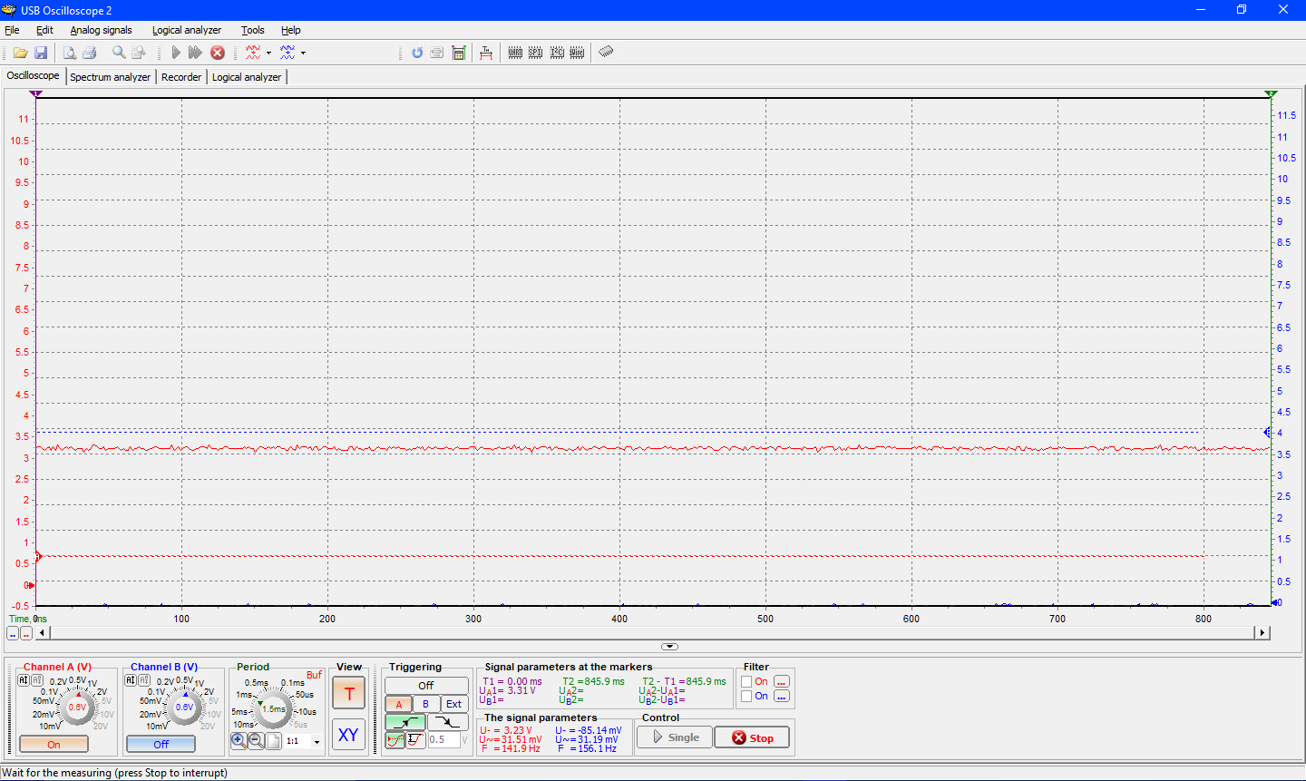
I am attempting to use the example project "ecap_capture_pwm_cpu01" on the TMS320F28377S microchip in Code Composer Studio. I am trying to generate a PWM. The project runs, but I have tested every single pin on the board with an oscilloscope, and not one of them is outputting a PWM.
What do I need to set up on the example project to make a PWM output?
I would like to schedule a screen share and have help properly setting up this project.
Here is a photo of the microchip, as well as the box it came in.
I'm running out of time. Can you please have someone connect with me via screen share and help me set up and get this PWM module working? Platforms I have access to are Skype, Google Hangouts and Team Viewer. If you have another I would be happy to set it up.
Hi Derek,
Ok, thanks for posting the kit info.
We are limited to support via the e2e here, but we'll do what we can.
--------------------------------------------
You said that the pin drives high? Is this only after you load and run the code?
------------------------------------------------
You can manually toggle a pin to verify hook-up by doing the following:
Launch a debug configuration, then 'connect', then 'load program' (or load symbols) from any project with bitfield defines
(.\ti\c2000\C2000Ware_1_00_02_00\device_support\f2837xs\examples\cpu1\ecap_capture_pwm\cpu01 project should be fine for this)
Then in the expressions window, set
This configures GPIO4 as a general purpose output. You should then be able to directly control the output state by changing
In the expressions window (1 = high, 0 = low):
--------------------------------------------------
Is the software you are trying to run coming from C2000ware, ControlSUITE, or somewhere else? It is probably a good idea to download the latest version of C2000ware (C2000Ware_1_00_02_00) if you haven't already.
--------------------------------------------------
Have you run a more basic example like?
\ti\c2000\C2000Ware_1_00_02_00\device_support\f2837xs\examples\cpu1\blinky
This is a good one to check because the LED won't blink if your target configuration/project doesn't have "_LAUNCHXL_F28377S" defined (which can cause issues with other projects).
I am running "ecap_capture_pwm_cpu01", which has come from ControlSUITE. Here is a screenshot of my oscilloscope, which shows that GPIO4 is driven high and maintains a constant output of 3.3 Volts.
I tried running the "blinky" example, and the LED blinked as expected once I defined "_LAUNCHXL_F28377S" in the project settings.
I defined "_LAUNCHXL_F28377S" in the settings of "ecap_capture_pwm_cpu01" as well, but the pin that should be oscillating, EPWM3a on GPIO4, is still only driven high as shown in the screen shot.
The documents and suggestions you are sending me are not helping. I was told in an email from TI technical support that I could request a screen share by posting here on e2e, so I know that someone can do a screen share with me. The email I recieved follows below:
"Hello Derek,
I would then check the system clock. Check that the PLL is correctly locked and the device is operating at the desired SYSCLK frequency.
InitSysCrtl(); In this function there is a function which adjusts the PLLSYSCLK, which is the same as the SYSCLK.
InitSysPll(XTAL_OSC, IMULT_40, FMULT_1, PLLCLK_BY_2); // 10 MHz* 40 * 1 /2 -> then the SYSCLK runs with 200MHz
Check out the suggestions below :
https://e2e.ti.com/support/microcontrollers/c2000/f/171/p/534845/1947860#1947860
Unfortunately I am not authorized to do any screen sharing. TI policy. To request that service please post this online at the e2e forums for C2000 chips : https://e2e.ti.com/support/microcontrollers/c2000/f/171 and if the personal agrees you can take the conversation offline and pursue it thereafter.
Regards,
Kishen Someshwar
TI Applications Support
Americas Customer Support Center
512-434-1560"
Please direct me to whoever it is that can provide me with this screen share service.
Thank you, the sample lines of code you have sent me are helping me make progress. I am now able to see the PWM oscillating. I am still stuck, I am unable to change the duty cycle.
Do you know which register to write to to set the duty cycle? My understanding is that it is CMPA, however when I insert the line "EPwm2Regs.CMPA.all", the PWM is not affected in any visual way. I have tried setting it to multiple values, but the duty cycle remains the same. Here is the code I am using:
EALLOW;
GpioCtrlRegs.GPAMUX1.bit.GPIO2 = 1; // Configure GPIO4 as EPWM3A
CpuSysRegs.PCLKCR2.bit.EPWM2 = 1; //ePWM clock enabled
CpuSysRegs.PCLKCR0.bit.TBCLKSYNC = 0; //ePWM clock gated
EPwm2Regs.TBCTL.bit.CTRMODE = 0; //ePWM up count
EPwm2Regs.TBPRD = 25; //ePWM period = 250 ePWM Clocks = 500 SYSCLKs
EPwm2Regs.AQCTLA.bit.PRD = 3; //toggle GPIO4 on ePWM period match
CpuSysRegs.PCLKCR0.bit.TBCLKSYNC = 1; //start ePWM clock
EPwm2Regs.TBCTL.bit.FREE_SOFT = 3; //ePWM free run
EPwm2Regs.CMPA.all = 6400;
EDIS;
Hi Derek,
The ePWM output can be toggled or driven high or driven low from a variety of events. Currently, the only event causing an output state change is this:
EPwm2Regs.AQCTLA.bit.PRD = 3; //toggle GPIO4 on ePWM period match
Which does not depend on the setting of comare A or B.
If you look at the other fields in the AQCTLA register, you will see that you can cause a variety of state changes at a variety of different points in the timer cycle. These include events based on compare A and B.
Note that because of
EPwm2Regs.TBCTL.bit.CTRMODE = 0; //ePWM up count
The epwm timer is only counting up. You can get more flexibility by setting the timer to up-down count mode instead.
Also note that this register controls the A output of ePWM2 (currently GPIO4) but that there is also an AQCTLB register which can be used to control a second ePWM pin (GPIO5) from the same time base. Both A and B outputs can take actions off of period, zero, compare A, and compare B events, so using compare B to control GPIO4 duty cycle would be just as valid.
My code now reads as follows:
"
EALLOW;
GpioCtrlRegs.GPAMUX1.bit.GPIO2 = 1; // Configure GPIO4 as EPWM3A
CpuSysRegs.PCLKCR2.bit.EPWM2 = 1; //ePWM clock enabled
CpuSysRegs.PCLKCR0.bit.TBCLKSYNC = 0; //ePWM clock gated
EPwm2Regs.TBCTL.bit.CTRMODE = 2; //ePWM up-down count
EPwm2Regs.TBPRD = 100000; //ePWM period = 250 ePWM Clocks = 500 SYSCLKs
EPwm2Regs.AQCTLA.bit.PRD = 3; //toggle GPIO4 on ePWM period match
EPwm2Regs.AQCTLA.bit.CAU = 3;
CpuSysRegs.PCLKCR0.bit.TBCLKSYNC = 1; //start ePWM clock
EPwm2Regs.TBCTL.bit.FREE_SOFT = 3; //ePWM free run
EPwm2Regs.CMPA.all = 75000;
EDIS;"
I have set TBPRD to be higher than CMPA, set TBCTL to up-down count, and set AQCTLA to toggle the signal. I still am unable to change the duty cycle.
Am I writing to the correct register? Right now, I am trying to set the duty cycle with "EPwm2Regs.CMPA.all = 75000;".
Hi Derek,
Have a look in the documentation and find the field width, in bits, of TBPRD and CMPA; I am pretty sure these are currently out-of-range.
I am currently looking up the field width in the technical reference manual.
In the mean time, I feel that "EPwm2Regs.CMPA.all" may not be the correct register to set the duty cycle. Can you verify whether it is? If it's not, which register should I be writing to?