Other Parts Discussed in Thread: MOTORWARE, TMDSHVMTRINSPIN
Hi,
I'm trying to use overmodulation on an ACIM project.
I'm using the following configuration:
- Custom board based on HvKit_rev1p1 / TMS320F28027FPTT
- Motoware 15
- Lab10a
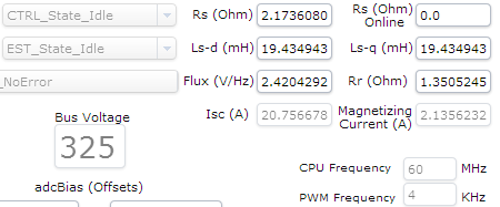
- ACIM motor Motovario TBS80D4 1.1kW (please find motor parameter below)
- This test is run at low voltage on a DC power supply (80 Vdc) with current limitation.
- The motor is free running at 465rpm with VsMax = 0.5
- The motor is free running at 540rpm with VsMax = 0.5774
#elif (USER_MOTOR == TecMotion_ACIM_TBS80D4)             	// Name must match the motor #define
#define USER_MOTOR_TYPE                 MOTOR_Type_Induction// Motor_Type_Pm (All Synchronous: BLDC, PMSM, SMPM, IPM) or Motor_Type_Induction (Asynchronous ACI)
#define USER_MOTOR_NUM_POLE_PAIRS       (2)                 // PAIRS, not total poles. Used to calculate user RPM from rotor Hz only
#define USER_MOTOR_Rr                   (1.3)           	// Identified phase to neutral in a Y equivalent circuit (Ohms, float)
#define USER_MOTOR_Rs                   (2.16)           	// Identified phase to neutral in a Y equivalent circuit (Ohms, float)
#define USER_MOTOR_Ls_d                 (0.0185)         	// For Induction, Identified average stator inductance  (Henry, float)
#define USER_MOTOR_Ls_q                 (0.0185)      		// For Induction, Identified average stator inductance  (Henry, float)
#define USER_MOTOR_RATED_FLUX           (0.8165*230.0/50.0) // sqrt(2/3)* Rated V (line-line) / Rated Freq (Hz)
#define USER_MOTOR_MAGNETIZING_CURRENT  (2.3)           		// Identified magnetizing current for induction motors, else NULL
#define USER_MOTOR_RES_EST_CURRENT      (1.5)               // During Motor ID, maximum current (Amperes, float) used for Rs estimation, 10-20% rated current
#define USER_MOTOR_IND_EST_CURRENT      (NULL)              // not used for induction
#define USER_MOTOR_MAX_CURRENT          (4.0)                // CRITICAL: Used during ID and run-time, sets a limit on the maximum current command output of the provided Speed PI Controller to the Iq controller
#define USER_MOTOR_FLUX_EST_FREQ_Hz     (5.0)               // During Motor ID, maximum commanded speed (Hz, float). Should always use 5 Hz for Induction.


#define USER_PWM_FREQ_kHz                (4.0) 				//30.0 Example, 8.0 - 30.0 KHz typical; 45-80 KHz may be required for very low inductance, high speed motors
This configuration works with no issue until I increase gMotorVars.OverModulation around the value 0.61.
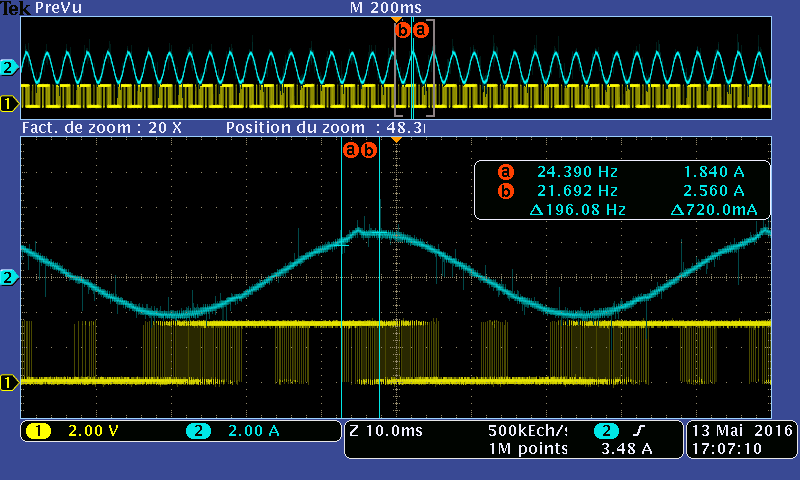
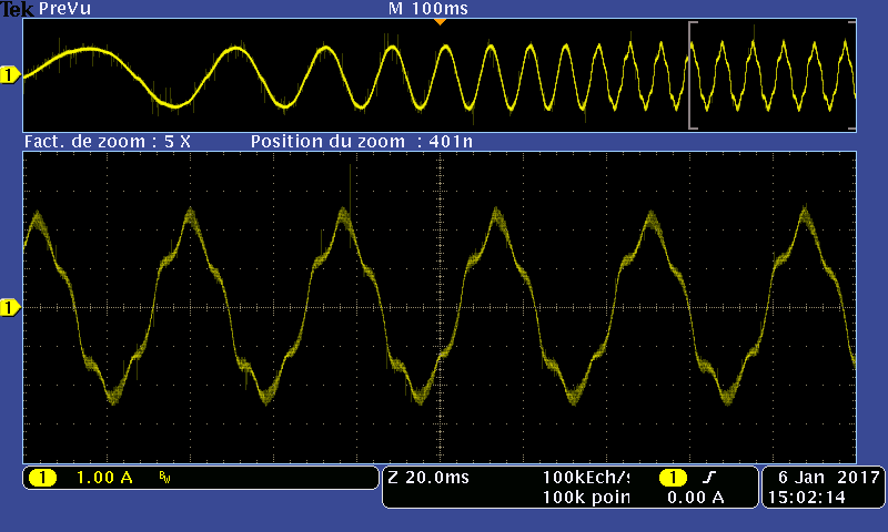
With this value sometime a "spike" appear always exactly on top of phase U current waveform (see zoom window below).
At the beginning I suspect the bootstrap capacitor to not be able to handle long pulses when the overmodulation enter in the trapezoidal phase.
Channel 1: PWMHU.
Channel 2: Output Current on phase U.
This capture show a zoom when the spike appear, I notice the PWMHU signal contain large pulse at that time compared to a "normal" waveform (check next scope capture below).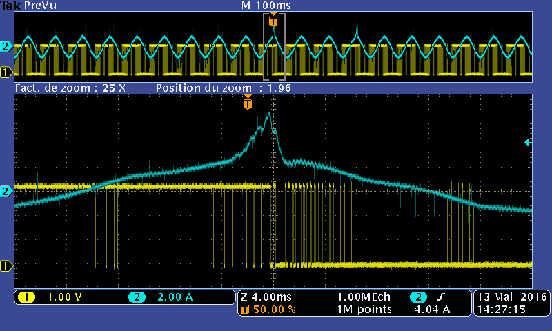
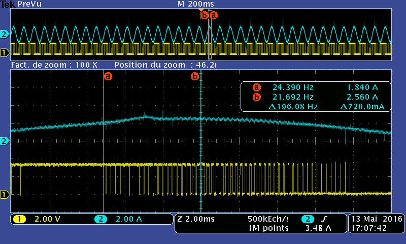
This capture show a zoom on a "normal" waveform.

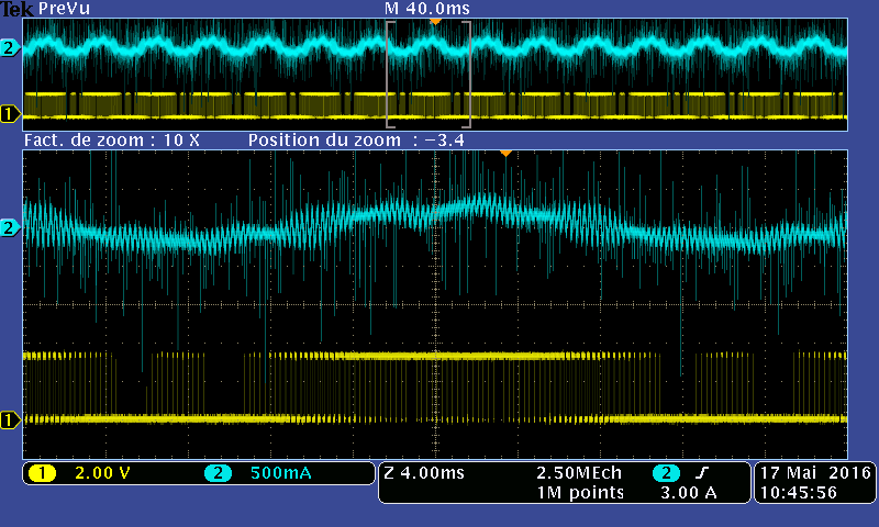
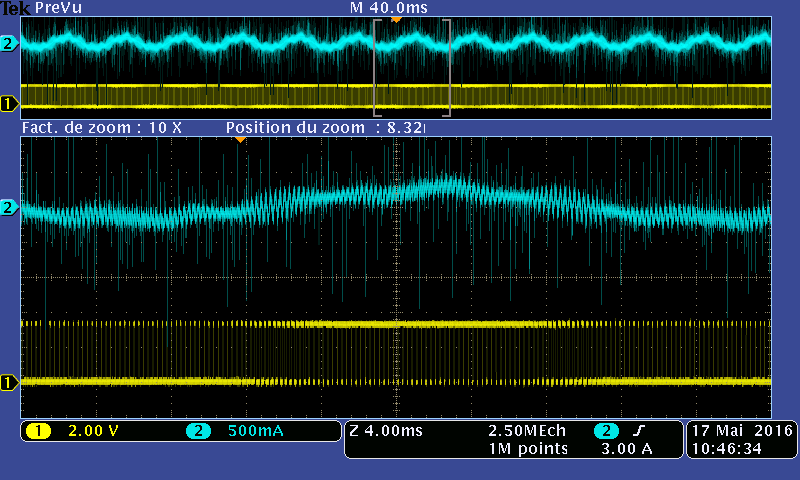
When I increase slightly the gMotorVars.OverModulation around the value 0.625 I can observe the same kind of spike on top of the phase V and W.
On the following capture, most of the spikes are on top of U phase (Channel 2 => Blue). Some spikes appears on top of V or W but less often (V phase => channel 1 => Yellow).

Because I suspect my custom hardware, I checked on the HvKit_rev1p1 and obtain the same behaviour with the kit.
On both hardware I'm able to run a brushless motor (the brushless motor is also running faster with the same voltage) on the full range of overmodulation (up to 0.67).
As described by Linley Rawlins in this tread https://e2e.ti.com/support/microcontrollers/c2000/f/902/t/499389 I tried to change:
- gCmpOffset value around the 1µs value
- svgencurrent.Minwith value around the 2µs value
But I didn't find any real improvement.
Do you have any idea of what happening?
thank you for your help,
Best regards,
Paul